All Kalashnikov assault rifles and their performance characteristics. AK74: purpose, combat properties and general arrangement of the machine gun, the principle of operation of automation; the order of incomplete disassembly and assembly The principle of operation of automation
Chapter III
PURPOSE, DEVICE OF PARTS AND MECHANISMS OF THE AUTOMATIC (MACHINE GUN) KALASHNIKOV, ACCESSORIES AND CARTRIDGES
Purpose, arrangement of parts and mechanisms of the machine gun (machine gun) Kalashnikov
11. Barrel(Fig. 27) serves to direct the flight of the bullet. Inside the barrel has a channel with four rifling, winding from left to right. The rifling serves to give the bullet a rotational motion. The gaps between the grooves are called fields. The distance between two opposite fields (in diameter) is called the caliber of the bore; for a machine gun (machine gun) it is 5.45 mm. In the breech, the channel is smooth and made in the shape of a cartridge case; this part of the channel serves to place the cartridge and is called the chamber. The transition from the chamber to the rifled part of the bore is called the bullet entry.
Outside, the barrel has a front sight base for a machine gun with a thread (for a machine gun, a thread on the muzzle) for screwing a muzzle brake-compensator on a machine gun (for a machine gun-flash suppressor) and
|
Rice. 27. Barrel: a - external view of the barrel of the machine gun; b - external view of the barrel of the machine gun; c - breech section; d - section of the barrel; 1 - rifled part; 2 - bullet entry; 3 - chamber; 4 - front sight base; 5 - gas chamber; 6 - coupling; 7 - sight block; 8 - recess for the barrel pin; 9 - thread; 10 - bipod base;
Rice. 28. Muzzle brake compensator and flash suppressor:
Rice. 29. Base of the front sight: a - machine gun; b - machine gun; 1 - emphasis with a recess for a ramrod; 2 - stop for a bayonet-knife with a hole for a ramrod; |
bushings for firing blank cartridges, a gas outlet, a gas chamber, a coupling, a sight block and a cutout for the ejector hook on the breech section. The base of the front sight, the gas chamber and the block of the sight are fixed to the barrel with pins. The machine gun, in addition, on the front of the barrel has a bipod base for attaching a bipod to the barrel with a hole for a ramrod and a ring with an eye to increase the reliability of fastening the ramrod. Muzzle brake-compensator machine (Fig. 28) serves to increase the accuracy of the battle and reduce the recoil energy. It has two chambers: front and rear (with a round hole in them for the bullet to fly out). The front chamber has a rim, on which the ring of the bayonet-knife is put on when it is attached to the machine gun, a rectangular groove into which the protrusion of the bayonet-knife enters, and two windows for the exit of powder gases. The rear chamber has two slots in front, and in the middle part - three compensation holes for the exit of powder gases. At the back, the muzzle brake compensator has an internal thread for screwing onto the base of the front sight, a recess into which the retainer enters and a circular bevel that facilitates the insertion and removal of the ramrod. Machine gun flash suppressor serves to reduce the size of the flame when fired. It has a thread for screwing onto the barrel, five recesses for the latch and five longitudinal slots for the release of gases. Front sight base(Fig. 29) has a stop with a notch for a ramrod, a hole for a front sight slide, a front sight guard and a retainer with a spring. The latch keeps the muzzle brake-compensator (flash suppressor) and the sleeve for firing blank cartridges from screwing. The machine, in addition, on the basis of the front sight has an emphasis for attaching a bayonet-knife with a hole for a ramrod. gas chamberserves to direct powder gases from the barrel to the gas piston bolt carrier. It has a gas outlet, a branch pipe with a channel for a gas piston and holes for the exit of powder gases. Coupling serves to attach the forearm to the machine gun (machine gun). It has a forearm lock, a swivel for a belt and a hole for a ramrod. The barrel is connected to the receiver by means of a pin and is not separated from it. 12. Receiver (fig. 30) serves for |


|
Rice. 30. Receiver: 1 - cutouts; 2 - reflective protrusion; 3 - limbs; |
connection of parts and mechanisms of the machine gun (machine gun), to ensure the closing of the bore by the bolt and locking the bolt. A trigger mechanism is placed in the receiver. The top of the box is closed with a lid. The receiver has: · inside - cutouts for locking the bolt, the rear walls of which are lugs; limbs and guides for guiding the movement of the bolt carrier and bolt; reflective protrusion to reflect the sleeves; jumper for fastening the side walls; a ledge for the hook of the store and one oval ledge on the side walls for the direction of the store; |

· top rear - grooves: longitudinal - for the heel of the guide rod of the return mechanism and transverse - for the cover receiver; tail with a hole for attaching the butt to the receiver;
· in the side walls - four holes each, three of them for the axes of the firing mechanism, and the fourth for the pins of the translator; on the right wall - two fixing recesses for setting the translator on automatic (AB) and single (OD) fire;
· below - a window for the store and a window for the trigger.
The machine with a folding butt, in addition, has holes for the latch and the latch of the butt (Fig. 33).
|
Rice. 31. Sight: a - automatic; b - machine gun; 1 - sight block; 2 - sector; 3 - aiming bar; 4 - collar; 5 - mane of the aiming bar; 6 - clamp latch; 7 - rear sight screw handwheel; 8 - rear sight |
In a machine gun with a folding buttstock, the receiver has a socket at the back for a left latch with a spring holding the stock in the folded position; on the right wall - a cutout for the right latch of the butt and a hole for pressing the right latch when it is recessed; on the left wall - an eye for attaching the butt and a hole for the front end of the left latch (Fig. 34 and 35). Attached to the receiver: a stock with a swivel, a pistol grip and a trigger guard with a magazine latch. For assault rifles (machine guns) with night sights, a bar is attached to the left side wall for attaching a night sight. 13. Sighting device serves to aim the machine gun (machine gun) when firing at targets at various ranges. It consists of a sight and a front sight. Aim(Fig. 31) consists of a sight block, a leaf spring, an aiming bar and a collar. Sight blockhas two sectors for giving the aiming bar a certain height, eyelets for attaching the aiming bar, holes for the pin and gas tube lock; inside - a socket for a leaf spring and a cavity for a bolt carrier; on the back wall- a semicircular cutout for the receiver cover. |

The sight block is put on the barrel and secured with a pin.
leaf spring is placed in the socket of the sight block and holds the aiming bar in the given position.
aiming bar has a mane with a slot for aiming and cutouts to hold the collar in established position by means of a spring latch. On the aiming bar (for a machine gun - from above, for a machine gun - from above and below) there is a scale with divisions from 1 to 10; scale numbers indicate firing ranges in hundreds of meters.
The machine gun, in addition, has the letter “P” on the aiming bar - a permanent setting of the sight, approximately corresponding to sight 4 (firing range 440 m).
At the machine gun, the aiming bar has a socket for the rear sight and at risk; on the wall of the nest of the rear sight there is a scale with ten divisions; each of which corresponds to two thousandths of the firing range.
Rear sightthe machine gun has a mane with a slot for aiming, a screw with a handwheel, a spring, a washer and a pin.
Clampput on the aiming bar and held in position by a latch. The latch has a tooth, which, under the action of a spring, jumps into the cutout of the aiming bar.
front sightscrewed into the runner, which is fixed at the base of the front sight. On the track and on the base of the front sight there are risks that determine the position of the front sight.
Attached to the machine gun (machine gun) device for shooting at night and in conditions of limited visibility(self-luminous nozzles). It consists of a folding rear sight with a wide slot, mounted on the mane of the aiming bar, and a wide front sight, put on top of the front sight of the weapon. Self-luminous dots are applied on the rear sight and front sight of the device.
In the device of the new sample, self-luminous stripes are applied: two horizontally located - on the rear sight and one vertically - on the front sight.
A device for shooting at night is installed on an automatic machine gun (machine gun) and verified when it enters the troops and is not separated from it during operation.
The combat of a weapon when firing with a fixture is basically the same as with an open sight. In the event of a significant deviation of the midpoint of impact in height, it is necessary to fix the weapon in the sighting machine, aim at the target and select the rear sight so that the aiming line with the open sight and the device coincide.
When shooting during the day, the rear sight and front sight of the device recline down. In this position, they do not interfere with the use of the sighting device of the machine gun (machine gun).
When firing at night and in conditions of limited visibility, the rear sight of the device turns up until it touches the mane of the aiming bar, and the front sight of the device moves up along the spring and is put on the front sight.
|
Rice. 32. Receiver cover: |
14. Receiver cover (Fig. 32) protects parts and mechanisms placed in the receiver from contamination. On the right side, it has a stepped cutout for the passage of ejected shells and for the movement of the bolt carrier handle; at the back - a hole for the protrusion of the guide rod of the return mechanism. The cover is held on the receiver by means of a semicircular cutout on the sight block, the transverse groove of the receiver and the protrusion of the guide rod of the return mechanism. |

15. Stock and pistol grip serve for the convenience of the operation of the machine gun (machine gun) when firing.
The permanent buttstock of the AK74, AK74N assault rifles (Fig. 33) and the RPK74, RPK74N machine guns (Fig. 34) has a swivel for a belt, a socket for an accessory case and a butt plate with a lid over the socket. In the nest of the butt, a spring is strengthened for pushing out the pencil case. The permanent butt of the machine gun can be wooden or plastic (for the machine gun - wooden).
The folding buttstock of the AKS74 and AKS74N assault rifles consists of an upper and lower rod, a butt plate, a clip and a tip, connected into one piece by welding. On the right side of the butt on the clip there is a swivel for a belt. In the folded position, the butt is held by a latch, and in the folded position, by a latch.
|
Rice. 33. The butt and pistol grip of the machine: a - a permanent (wooden) butt (in section);
Rice. 35. Folding the butt of a machine gun: 1 - butt; 2- receiver; 3 - pistol grip; 4 - hole in the wall of the receiver |
Rice. 34. Butt and pistol grip machine gun: a - a permanent butt (in the section); b - a folding butt (in the folded position); 1 - swivel for a belt; 2 - socket for accessories; 3 - butt plate; 4 - cover; 5 - spring for pushing out the accessory case; 6 - protrusion of the butt with ears; 7 - eye of the receiver; 8 - right latch of the butt with a spring;
Rice. 36. Machine gun bipod: 1 - bipod base; 2 - legs; 3 - spring; 4 - ledge; |


To fold the butt, it is necessary to drown the latch (in this case, the latch will disengage from the butt tip) and turn the butt to the left around the axis until the butt is secured with a latch located on the left wall of the receiver.
To recline the butt, you need to pull the latch back and turn the butt to the right until it is secured with a latch.
The folding butt of the RPKS74 and RPKS74N machine guns, in addition to the machine gun specified for the permanent butt, has a protrusion for the right butt latch holding the butt in the folded position, lugs for attaching the butt to the receiver, and for the RPKS74N, it also has a recess, which includes a strap for attaching a night sight when the butt is folded.
To fold the butt, it is necessary to drown the right latch of the butt with a punch or a cartridge bullet through the hole in the right wall of the receiver (Fig. 35) and turn the butt to the left until it is secured with the left latch in the folded position.
To recline the butt, you need to press your finger on the back of the latch with a notch in left side and turn the butt to the right until it is secured with the right latch.
16. Machine gun bipod(Fig. 36) serves as an emphasis when shooting. It has a base, two legs with skids for resting on the ground and protrusions for fixing the legs in the folded position, a spring for spreading the legs, a spring fastener on the left leg for fastening the legs in the folded position. The bipod is not separated from the machine gun.
17. Bolt carrier with gas piston(Fig. 37) serves to actuate the shutter and trigger mechanism.
|
Rice. 37. Bolt frame with gas piston:
Rice. 38. Shutter: a ~ shutter core; b- drummer; in - ejector; 1 - cutout for the sleeve; 2-cutout for the ejector; 3- leading protrusion; 4- hole for the ejector axis; 5 - combat ledge; 6 - longitudinal groove for a reflective ledge; 7 - ejector spring; 8 ~ ejector axis; |
The shutter frame has: inside - a channel for the return mechanism, and a channel for the shutter; rear - safety ledge; on the sides - grooves for the movement of the bolt frame along the limbs of the receiver; on the right side - a ledge for lowering (turning) the self-timer lever and a handle for reloading the machine gun (machine gun); below - a figured cutout for placing the leading protrusion of the shutter in it and a groove for the passage of the reflective protrusion of the receiver. A gas piston is fixed in front of the bolt frame. 18. Shutter(Fig. 38) serves to send the cartridge into the chamber, close the bore, break the primer and remove the cartridge case (cartridge) from the chamber. It consists of a core, a drummer, an ejector with a spring and an axis, and a stud. shutter framehas: on the front cut - a cylindrical cutout for the bottom of the sleeve and a groove for the ejector; on the sides - two lugs, which, when the bolt is locked, go into the cutouts of the receiver; on top - a leading ledge for turning the shutter when locking and unlocking; on the left side - a longitudinal groove for the passage of the reflective protrusion of the receiver (the groove at the end is expanded to ensure the rotation of the bolt when locking); in the thickened part of the shutter body there are holes for the ejector axis and studs. Inside the frame of the shutter has a channel for placing the drummer. |


Drummerhas a striker and a ledge for a hairpin.
Ejectorwith a spring serves to remove the sleeve from the chamber and hold it until it meets the reflective protrusion of the receiver. The ejector has a hook for gripping the sleeve, a socket for the spring and a cutout for the axle.
Hairpinserves to secure the drummer and the ejector axis.
|
Rice. 39. Return mechanism: 1 - return spring; 2 - guide rod;
Rice. 40. Gas tube with handguard: 1- gas tube; 2 - guide ribs for the gas piston; 3 - front coupling; 4 - handguard; 5 - rear coupling; 6 - protrusion; 7 - leaf spring
Rice. 41. Parts of the firing mechanism: A - trigger; b - mainspring; c - trigger; |
19. Return mechanism (Fig. 39). serves to return the bolt carrier with the bolt to the forward position. It consists of a return spring, a guide rod, a movable rod and a clutch. guide rod has a spring stop at the rear end, a heel with protrusions for connection with the receiver and a protrusion for holding the receiver cover. Movable rod at the front end has bends for putting on the clutch. 20. Gas tube with handguard (Fig. 40) consists of a gas tube, front and rear couplings, a handguard, a metal half ring and a leaf spring. gas tubeserves to guide the movement of the gas piston. It has guide ribs. The front end of the gas tube is put on the branch pipe of the gas chamber. barrel pad serves to protect the hands of the submachine gunner (machine gunner) from burns when firing. It can be wooden or plastic for a machine gun (wooden for a machine gun) and has a groove in which a metal semi-ring is fixed, pressing the handguard from the gas tube (this eliminates the appearance of the rocking of the lining when the wood dries out). The handguard is attached to the gas tube by means of front and rear couplings; the rear coupling has a protrusion against which the gas pipe contactor rests; leaf spring eliminates the longitudinal pitching of the tube. 21. Trigger mechanism (Fig. 41) serves to release the trigger from the combat cocking or from the self-timer cocking, striking the striker, ensuring automatic or single fire, stopping firing, preventing shots when the bolt is unlocked and for setting the machine gun (machine gun) on the safety. |


The trigger mechanism is placed in the receiver, where it is attached with three interchangeable axles, and consists of a trigger with a mainspring, a trigger retarder with a spring, a trigger, a single-fire whisper with a spring, a self-timer with a spring, a translator and a tubular axis.
triggerwith a mainspring is used to strike the drummer. The trigger has a combat cocking, self-timer cocking, trunnions and a hole for the axis. The mainspring is put on the trigger trunnions and with its loop acts on the trigger, and with its ends - on the rectangular ledges of the trigger,
trigger retarder serves to slow down the forward movement of the trigger in order to improve the accuracy of combat when firing from stable positions. It has front and rear lugs, axle hole, spring and latch.
Trigger serves to hold the trigger on the cocking and to pull the trigger. It has a figured protrusion, a hole for the axle, rectangular protrusions and a tail. With his figured protrusion, he keeps the trigger on the cocking.
Single Fire Whisper serves to hold the trigger after a shot in the rearmost position, if the trigger was not released during single fire. It is on the same axis as the trigger. The sear of a single fire has a spring, a hole for the axis and a cutout, which includes the interpreter sector when conducting automatic fire and stops the sear. In addition, the notch limits the sector to rotate forward when the translator is on the safety lock.
Self-timerserves to automatically release the trigger from the self-timer cocking when firing in bursts, as well as to prevent the trigger from being released when the bore is not closed and the bolt is not locked. It has a sear for holding the trigger while the self-timer is cocked, a lever for turning the self-timer with the projection of the bolt carrier when it approaches the forward position, and a spring.
On the same axis with the self-timer is its spring. Its short end is connected to the self-timer, and its long end runs along the left wall of the receiver and enters the annular grooves on the axes of the self-timer, trigger and trigger, keeping the axes from falling out.
|
Rice. 42. Handguard (wooden): 1 - finger rest; 2 - ledge; 3 - leaf spring; 4 - hole for ramrod
Rice. 43. Shop: 1- housing; 2- cover; 3- locking bar; 4- spring; 5 - feeder; 6 - support ledge; 7 - hook |
Interpreterserves to install the machine gun (machine gun) on automatic or single fire, as well as on the fuse. It has a sector with trunnions that fit into the holes in the walls of the receiver. The lower position of the translator corresponds to setting it to a single fire (OD), the middle position to automatic fire (AB) and the upper position to the fuse. 22. Handguard(Fig. 42) serves for the convenience of action and to protect the hands of the submachine gunner (machine gunner) from burns. It can be wooden or plastic for a machine gun (wooden for a machine gun). The fore-end is attached to the barrel from below using a coupling and to the receiver - by means of a protrusion that enters the socket of the receiver. In the body of the forearm there is a through hole for a ramrod. At the rear of the forearm there are cutouts and a notch into which the leaf spring is placed. The spring serves to eliminate the pitching of the forearm. The cutouts on the handguard and handguard form windows for cooling the barrel and gas tube when firing. The plastic handguard has a metal shield designed to reduce the heat of the handguard when firing. |


23. Shop(Fig. 43) serves to place cartridges and feed them into the receiver. It consists of a plastic body, a cover, a locking plate, a spring and a feeder.
The magazine body connects all parts of the magazine; his side walls they have bends on top (on the neck) to keep the cartridges from falling out and protrusions that limit the rise of the feeder; on the front wall there is a hook, and on the back - a support ledge, through which the magazine is attached to the receiver. On the back wall of the case at the bottom there is a control hole for determining the completeness of the magazine's equipment with cartridges.
From below the case is closed by a cover. The cover has a hole for the protrusion of the locking bar.
A feeder and a spring with a locking bar are placed inside the housing. The feeder is held at the upper end of the spring by means of an internal fold on the right wall of the feeder; the feeder has a protrusion that provides a staggered arrangement of cartridges in the magazine. The locking bar is permanently attached to the lower end of the spring and, with its protrusion, keeps the magazine cover from moving.
|
Rice. 44. Bayonet: a - blade; b - handle; 1 - cutting edge; 2 - saw;
Rice. 45. Scabbard: 1 - pendant with a loop-fastener and a carabiner;
Rice. 46. Affiliation: 1 - ramrod; 2 - wiping; 3 - brush; 4 - screwdriver; 5 - punch; 6 - pencil case; 7 - cover; 8 - oiler; 9 - clip; |
24. Bayonet(Fig. 44) is attached to the machine to defeat the enemy in battle. In addition, it is used as a knife, saw (for cutting metal) and scissors (for cutting wire). The wires of the lighting network must be cut one at a time, after removing the belt from the bayonet-knife and the pendant from the sheath. When cutting the wire, make sure that your hands do not touch the metal surface of the bayonet-knife and scabbard. Making passages in electrified wire obstacles with a bayonet-knife not allowed. The bayonet-knife consists of a blade and a handle. on the bladethere is a cutting edge, a saw, a sharpened edge, which, in combination with a scabbard, is used as scissors, a hole into which a protrusion-axis of the scabbard is inserted. Leverserves for the convenience of action and for adjoining the bayonet-knife to the machine. There is a belt on the handle for easy handling of the bayonet-knife; front - ring and ledge for attachment to muzzle brake compensator and belt hook; behind a metal lug with a connecting screw. On the tip there are longitudinal grooves with which the bayonet is put on the corresponding protrusions on the base of the front sight, a latch, a safety protrusion and a hole for the belt. Sheath(Fig. 45) are used to carry a bayonet-knife on the waist belt. In addition, they are used together with a bayonet-knife for cutting wire. The scabbard has a suspension with a loop, a protrusion-axis, an emphasis to limit the rotation of the bayonet-knife when it acts like scissors; inside the scabbard there is a leaf spring with a Lock to keep the bayonet-knife from falling out. Belonging to the machine gun (machine gun) 25. Belonging (Fig. 46) serves for disassembly, assembly, cleaning, lubrication of the machine gun (machine gun) and accelerated loading of the magazine with cartridges. Accessories include: a ramrod, a wipe, a brush, a screwdriver, a punch, a pencil case, an oiler, clips and an adapter. |


Ramrodused for cleaning and lubricating the barrel bore, as well as the channels and cavities of machine gun (machine gun) parts. It has a head with a punch hole, a thread for screwing a wipe or a brush.
Rubbingused for cleaning and lubricating the bore, channels and cavities of other parts of the machine gun (machine gun). It has an internal thread for screwing onto a ramrod and a slot for rags or tow.
brushused to clean the bore with RFS solution.
Screwdriver and punch used for disassembly and assembly of the machine gun (machine gun). The cutout at the end of the screwdriver is designed for screwing in and unscrewing the front sight, and the side cutout is for fixing the wipe on the ramrod. For ease of use, a screwdriver is inserted into the side holes of the case. When cleaning the bore, a screwdriver is inserted into the case over the head of the ramrod.
Pencil caseserves for storage of rubbing, a brush, a screw-driver and a drift. It is closed with a lid.
The case is used as a handle for a screwdriver when screwing in and unscrewing the front sight and for turning the gas pipe contactor, as well as a handle for a ramrod.
The case has through holes into which a ramrod is inserted when cleaning the machine gun (machine gun), oval holes for a screwdriver and a rectangular hole for turning the gas tube connector when disassembling and assembling the machine gun (machine gun).
Single neck oiler serves to store lubricant, it is carried in the pocket of a shopping bag.
clipserves for carrying cartridges and accelerated equipment of the magazine with cartridges. The clip holds 15 rounds. It has two longitudinal grooves and a leaf spring that keeps the cartridges from falling out. In addition, the leaf spring provides a strong connection of the cage with the adapter.
Adapterserves to connect the clip with the magazine when equipping it with cartridges. It has: from the bottom (broadened part) two bends that fit into the corresponding grooves on the neck of the store; on top - two longitudinal grooves for the clip, a hole for the clip spring and a stop that limits the progress of the clip when it is inserted into the adapter.
5.45mm live ammunition Kalashnikov
26. Live cartridge (Fig. 47) consists of a bullet, cartridge case, powder charge and capsule.
|
Rice. 47. Live cartridge: 1 - bullet; 2 - sleeve; 3 - powder charge; 4 - primer; |
Rice. 48. Bullets: a - ordinary with a steel core; b - tracer: 1 - shell; 2 - steel core; 3 - lead jacket; 4 - core (lead); 5 - tracer composition |

27. 5.45 mm rounds are issued with ordinary and tracer bullets. The head of the tracer bullet is painted in green color. To simulate shooting, blank (without a bullet) cartridges are used, which are fired using a special sleeve.
ordinarybullet(Fig. 48, a) is designed to defeat enemy manpower located openly and behind obstacles pierced by a bullet.
An ordinary bullet consists of a tombac-coated steel jacket and a steel core. There is a lead jacket between the sheath and the core.
tracer bullet (Fig. 48.6) is also designed to defeat enemy manpower. In addition, when a bullet is flying in the air, its burning tracer composition at firing ranges up to 800 m leaves a luminous trail, which allows for fire correction and target designation.
In the shell of a tracer bullet, a core is placed in the head part, and a checker of a pressed tracer composition is placed in the bottom part. During the shot, the flame from the powder charge ignites the tracer composition, which, when the bullet flies, gives a luminous trail.
28. Sleeve serves to connect all parts of the cartridge, protect the powder charge from external influences and to eliminate the breakthrough of powder gases towards the shutter. It has a body for placing a powder charge, a muzzle for fixing a bullet and a bottom. Outside, at the bottom of the sleeve, an annular groove is made for the ejector hook. At the bottom of the sleeve there is a nest for the primer, an anvil and two seed holes.
29. Powder charge serves to communicate translational motion to the pool; it consists of gunpowder spherical granulation.
30. Capsule serves to ignite the powder charge. It consists of a brass cap, an impact composition pressed into it and a foil circle covering the impact composition.
31. Capping of 5.45-mm cartridges is made in wooden boxes. The box contains two hermetically sealed metal boxes of 1080 rounds each; cartridges in boxes are packed in cardboard packs of 30 pieces. In total, 2160 rounds are placed in the box.
On the side walls of the boxes, in which cartridges with tracer bullets are sealed, a green stripe is applied. Each box has a knife to open the box.
Introduction
The 5.45-mm Kalashnikov assault rifle is an individual weapon and is designed to destroy enemy manpower. To defeat the enemy in hand-to-hand combat, a bayonet-knife is attached to the machine gun. For shooting and observation in conditions of natural night illumination, the AK-74N, AKS-74N assault rifles are equipped with a universal night shooting sight (NSPU).
An additional letter at the abbreviated name of the machine means: "H" - with a night sight; "C" - with a folding butt.
For firing from a machine gun, cartridges with ordinary (with a steel core) and tracer bullets are used.
Automatic or single fire is carried out from the machine gun. Automatic fire is the main type of fire: it is short (up to 5 shots) and long - up to 10 shots, in bursts and continuously. The supply of cartridges during firing is made from a box magazine with a capacity of 30 rounds.
Question number 1. Tactical specifications AK-74 assault rifle
Ballistic and structural data of the 5.45 mm Kalashnikov assault rifle (AK-74 and AKS-74) and the 5.45 mm cartridge for it are shown in Table 1.
Beginning of table 1
Tactical and technical characteristics of the AK-74 assault rifle
End of table 1
| No. p / p | Name of data | Data value |
| Range to which the lethal effect of the bullet is maintained, m | ||
| Sighting range bullet flight, m | ||
| Machine weight, kg: - with empty plastic magazine - with equipped plastic magazine | 3,3 3,6 | |
| Magazine capacity, cartridges | ||
| Plastic magazine weight, kg | 0,23 | |
| Caliber, mm | 5,45 | |
| The length of the machine, mm: - with attached bayonet-knife and folded butt - without bayonet-knife and folded butt - with folded butt | ||
| Barrel length, mm | ||
| The length of the rifled part of the barrel, mm | ||
| Number of grooves, pcs. | ||
| Sighting line length, mm | ||
| Cartridge weight, g | 10,2 | |
| Bullet weight with steel core, g | 3,4 | |
| Powder charge weight, g | 1,45 |
Conclusion: in this issue the ballistic and structural data of the 5.45-mm Kalashnikov assault rifle were considered.
Question number 2. The device and purpose of the main elements of the AK-74 assault rifle
The device of the Kalashnikov assault rifle AK-74
The main parts and mechanisms of the machine and its accessories are shown in fig. one.
Rice. 1. The main parts and mechanisms of the machine and its accessories
The machine consists of the following main parts and mechanisms:
receiver covers;
shutter;
return mechanism;
Shop.
In addition, the machine has a muzzle brake-compensator and a bayonet-knife. The machine kit also includes:
Affiliation;
Shopping bag.
In addition, a rifle case with a pocket for a magazine is included in the set of a machine gun with a folding butt, and a universal night sight is also included in the machine set with a night sight.
The purpose of the main elements of the AK-74
2.2.1. Trunk(Fig. 2) serves to direct the flight of the bullet. Inside the barrel has a channel with four rifling, winding from left to right. The rifling serves to give the bullet a rotational motion. The gaps between the grooves are called fields. The distance between two opposite fields (in diameter) is called the caliber of the bore. In the machine it is equal to 5.45 mm. In the breech, the channel is smooth and made in the shape of a cartridge case. This part of the channel serves to place the cartridge and is called the chamber. The transition from the chamber to the rifled part of the bore is called the bullet entry.
Rice. 2. Barrel:
a- external view; b- breech section; c - section of the trunk;
1 - threaded part; 2 - pool entrance; 3 - chamber; 4 - carving;
5 - the base of the front sight; 6 - gas chamber; 7 - coupling;
8 - sight block; 9 - notch for the barrel stud
Outside the trunk has:
Thread on the muzzle;
Fly base;
Gas outlet;
gas chamber;
Coupling;
Sight block;
Cutout for the ejector hook on the breech section.
The base of the front sight, the gas chamber and the block of the sight are fixed to the barrel with pins.
The thread (left) on the muzzle serves to screw on the compensator and bushing when firing with blank cartridges. To protect the thread from damage, it is screwed onto the barrel barrel sleeve.
Muzzle brake compensator serves to increase the accuracy of combat when firing bursts from unstable positions (on the move, standing, kneeling). It has a cylindrical part for screwing the compensator onto the barrel. At the back of the cylindrical part there is a groove into which the latch enters, holding the compensator on the barrel in a predetermined position. A groove is made inside the protrusion, forming a compensation chamber and a collar. After the bullet leaves the bore, the powder gases, entering the compensation chamber, create excess pressure, which deflects the muzzle of the machine towards the protrusion (left - down). Outside, the ledge has a T-slot for holding the canister cover while cleaning the barrel.
Front sight base(Fig. 3) has:
Emphasis for the ramrod and the handle of the bayonet-knife;
Hole for the front sight;
Front sight safety;
Spring retainer.
Rice. 3. Front sight base with barrel sleeve:
1 - emphasis for a ramrod and a bayonet-knife;
2 - polozok with a front sight; 3 - fuse fuse; 4 - retainer;
5 - barrel sleeve
The latch keeps the sleeve for firing blank cartridges, the compensator and the barrel sleeve, as well as the canister cover from turning when cleaning the barrel bore, from screwing off the barrel.
Gas chamber serves to direct powder gases from the barrel to the gas piston of the bolt carrier.
She has:
Branch pipe with a channel for a gas piston and holes for the exit of powder gases;
Inclined gas outlet;
Emphasis for the handle of a bayonet-knife.
A ramrod is placed in the lug of the stop.
Coupling serves to attach the forearm to the machine. She has:
Forend lock;
Antab for a belt;
Hole for a ramrod.
The barrel is connected to the receiver by means of a pin and is not separated from it.
2.2.2. Receiver(fig. 4) serves for:
Connections of parts and mechanisms of the machine;
Ensuring the closing of the bore with a shutter;
Shutter lock.
Rice. 4. Receiver:
1 - cutouts; 2 - reflective ledge; 3 - bends; 4 - guide ledge;
5 - jumper; 6 - longitudinal groove; 7 - transverse groove; 8 - store latch;
9 - trigger guard; 10 - pistol grip; 11 - butt
A trigger mechanism is placed in the receiver. From above it is closed with a lid.
The receiver has:
1. Inside:
Cutouts for locking the shutter, the rear walls of which are lugs;
Bends and guides for guiding the movement of the bolt carrier and bolt;
- reflective protrusion to reflect the sleeves;Jumper for fastening the side walls;
Protrusion for the hook of the store;
One oval ledge on the side walls to guide the store.
2. Back top:
Longitudinal groove - for the heel of the guide rod of the return mechanism;
Transverse groove - for the cover of the receiver;
Tail with a hole for mounting the butt in the receiver.
3. In the side walls - four holes, three of them for the axes of the firing mechanism, and the fourth for the pins of the translator.
4. On the right wall - two fixing recesses for setting the translator on automatic (AB) and single (OD) fire. The machine with a folding buttstock also has holes for the connecting sleeve and holes for the protrusions of the butt locks.
5. Below - a window for the store and a window for the trigger.
Attached to the receiver is a buttstock, a pistol grip and a trigger guard with a magazine latch.
2.2.3. sighting device serves to aim the machine gun when firing at targets at various distances. It consists of a sight and a front sight.
Aim(Fig. 5) includes:
Sight block;
leaf spring;
aiming bar;
Clamp.
Sight block It has:
Two sectors to give the aiming bar a certain height;
Eyelets for attaching the aiming bar;
Holes for the pin and the gas pipe contactor;
Inside - a socket for a leaf spring and a cavity for the bolt carrier;
On the back wall there is a semicircular cutout for the receiver cover.
The sight block is put on the barrel and secured with a pin.
leaf spring is placed in the socket of the sight block and holds the aiming bar in the given position.
Rice. 5. Sight:
1 - chapel block; 2 – sector; 3 - aiming bar; 4 - clamp;
5 - mane of the aiming bar; 6 - clamp latch
The aiming bar has:
Mane with a slot for aiming;
Cut-outs to hold the collar in the installed position by means of a latch with a spring.
On the aiming bar there is a scale with divisions from 1 to 10 and the letter "P". The scale numbers indicate firing ranges in hundreds of meters; "P" - permanent setting of the sight, corresponding to sight 3.
Clamp put on the aiming bar and held in position by a latch. The latch has a tooth, which, under the action of a spring, jumps into the cutout of the aiming bar.
front sight screwed into the runner, which is fixed at the base of the front sight. On the track and on the base of the front sight there are risks that determine the position of the front sight.
The latest releases of assault rifles are equipped with devices for shooting at night (self-luminous nozzles). Each device consists of a folding rear sight with a wide slot, mounted on the mane of the aiming bar, and a wide front sight, put on the front sight of the weapon from above. Luminous dots are applied on the rear sight and front sight of the device.
Devices for shooting at night are installed on machine guns when they enter the troops and are not separated from them during operation.
2.2.4. receiver cover(Fig. 6) protects parts and mechanisms placed in the receiver from contamination.
Rice. 6. Receiver cover:
1 – stepped cut; 2 - hole; 3 - stiffening rib
On the right side, it has a stepped cutout for the passage of ejected shells and for the movement of the bolt carrier handle. Behind - a hole for the protrusion of the guide rod of the return mechanism.
The cover is held on the receiver using a semicircular cutout on the block of the sight, the transverse groove of the receiver and the protrusion of the guide rod of the return mechanism.
2.2.5. Stock and pistol grip(Fig. 7) serve for the convenience of automatic operation.
Rice. 7. Stock and pistol grip:
a- permanent butt; b- folding butt;
1 - swivel for a belt; 2 - socket for accessories; 3 - butt plate;
4 - lid; 5 – a spring for pushing out a case with accessories;
6 - pistol grip;
2.2.6. Bolt carrier with gas piston serves to actuate the shutter and trigger mechanism (Fig. 8).
Rice. 8. Bolt carrier with gas piston:
1 – shutter channel; 2 - safety ledge; 3 - lowering protrusion
self-timer lever; 4 - a groove for bending the receiver; 5 - handle;
6 - figured cut; 7 - a groove for a reflective protrusion; 8 - gas piston.
The shutter frame has:
Inside - channels for the return mechanism and for the shutter;
Behind - a safety ledge;
On the sides - grooves for the movement of the bolt frame along the limbs of the receiver;
On the right side - a ledge for lowering (turning) the self-timer lever and a handle for reloading the machine gun;
Below - a figured cutout for placing the leading protrusion of the shutter in it and a groove for the passage of the reflective protrusion of the receiver;
In the front is a gas piston.
2.2.7. Gate(fig. 9) serves for:
Sending a cartridge into the chamber;
Closing the bore;
Breaking the capsule;
Extraction from the chamber of the sleeve (cartridge).
The shutter consists of a core, a drummer, an ejector with a spring and an axis, and a stud.
shutter frame It has:
1. On the front cut:
Two cylindrical cutouts for the bottom of the sleeve and for the ejector;
Two lugs that, when the bolt is locked, go into the cutouts of the receiver.
2. Above - a leading ledge for turning the shutter when locking and unlocking.
3. On the left side - a longitudinal groove for the passage of the reflective protrusion of the receiver (the manhole at the end is expanded to ensure the rotation of the bolt when locking).
4. In the thickened part of the shutter frame there are holes for the ejector axis and studs.
5. Inside the channel for placing the drummer.
Rice. 9. Shutter:
a- shutter frame; b- ejector;
1 - cutout for the sleeve; 2 – cutout for the ejector; 3 - leading speech;
4 – an opening for an ejector axis; 5 - combat ledge; 6 - longitudinal groove
for a reflective protrusion; 7 – ejector spring;
8 - the axis of the ejector; 9 - hairpin
Drummer has a striker and a ledge for a hairpin.
Spring ejector serves to extract the sleeve from the chamber and hold it until it meets the reflective ledge of the receiver. The ejector has a hook for gripping the sleeve, a socket for the spring and a cutout for the axle.
Hairpin serves to secure the drummer and the ejector axis.
2.2.8. Return mechanism(Fig. 10) serves to return the bolt carrier with the bolt to the forward position.
Rice. 10. Return mechanism:
1 – return spring; 2 - guide rod;
3 - movable rod; 4 – clutch
It consists of a return spring, a guide rod, a movable rod and a clutch.
guide rod has a spring stop at the rear end, a heel with projections for connection with the receiver and a projection for holding the receiver cover.
Movable rod at the front end has bends for putting on the clutch.
2.2.9. Gas tube with handguard(Fig. 11) consists of a gas tube, front and rear couplings, a handguard and a metal half ring.
Rice. 11. Gas tube with handguard:
1 - gas pipe; 2 - guide ribs for the gas piston;
3 – front coupling; 4 - barrel pad;
5 – back coupling; 6 - protrusion
gas tube serves to guide the movement of the gas piston. It has guide ribs. The front end of the gas tube is put on the branch pipe of the gas chamber.
barrel pad serves to protect the submachine gunner's hands from burns when firing. It has a groove in which a metal half-ring is fixed, which presses the handguard from the gas tube (this eliminates the appearance of the rocking of the lining when the wood dries out).
barrel pad mounted on the gas pipe by means of front and rear couplings; the rear coupling has a protrusion against which it abuts against the gas pipe contactor.
2.2.10. trigger mechanism(fig. 12) serves for:
Release the trigger from the combat cocking or self-timer cocking;
Striking a striker;
Ensuring automatic or single fire;
Cessation of shooting;
To prevent shots when the shutter is unlocked;
To put the machine on the fuse.
trigger mechanism is placed in the receiver, where it is attached with three interchangeable axles, and consists of:
Hammer with mainspring;
trigger retarder with spring;
Trigger;
Whispered single fire with a spring;
Self-timer with spring;
translator.
trigger with mainspring serves to strike a striker. The trigger has a combat cocking, self-timer cocking, trunnions and a hole for the axis. The mainspring is put on the trunnions of the trigger and acts on the trigger with its loop, and with its ends - on the rectangular ledges of the trigger.
Rice. 12. Parts of the firing mechanism:
a- trigger; b- mainspring; in- trigger; G- whisper of a single fire;
d- self-timer; e- self-timer spring; well- axes; h- the spring whispered a single fire;
and- trigger retarder; to- trigger retarder spring;
1 - combat platoon; 2 - self-timer platoon; 3 - curved ends 4 - the loop;
5 - figured protrusion; 6 - rectangular ledges; 7 - tail; 8 - cutout;
9 - whispered; 10 - lever arm; 11 - latch; 12 - front protrusion
trigger retarder serves to slow down the movement of the trigger forward in order to improve the accuracy of the battle during automatic fire.
He has:
Front and rear protrusions;
Axle hole;
spring;
A latch attached to the rear ledge with a stud.
Trigger serves to hold the trigger on the cocking and
to pull the trigger. He has:
Figured ledge;
Axle hole;
Rectangular ledges;
A tail that holds the trigger on the cocking with a curly ledge.
Single Fire Whisper serves to hold the trigger after a shot in the rearmost position, if the trigger was not released during single fire. It is on the same axis as the trigger.
The sear of a single fire has:
spring;
Axle hole;
The cutout, which includes the sector of the translator when conducting automatic fire and stops the sear.
In addition, the notch limits the sector to rotate forward when the translator is on the safety lock.
Self-timer with spring serves to automatically release the trigger from the self-timer cocking when firing in bursts, as well as to prevent the trigger from being released when the bore is not closed and the bolt is not locked.
He has:
Sear for holding the trigger on the self-timer cocking;
A lever for turning the self-timer with a projection of the bolt carrier when it approaches the forward position;
spring.
On the same axis with the self-timer is its spring. Its short end is connected to the self-timer, and its long end runs along the left wall of the receiver and enters the annular grooves on the axes of the self-timer, trigger and trigger, keeping the axes from falling out.
Interpreter serves to install the machine:
On automatic fire;
On a single fire;
To the fuse.
It has a sector with trunnions, which are placed in the holes in the walls of the receiver. The lower position of the translator corresponds to setting it to a single fire (OD), the middle position to automatic fire (AB) and the upper position to the fuse.
2.2.11. handguard(Fig. 13) serves for ease of operation and to protect the submachine gunner's hands from burns. It is attached to the barrel from below using a coupling and to the receiver by means of a protrusion included in the socket of the receiver. In the forearm groove there is a metal gasket to support the barrel, and on the sides there are finger rests. The cutouts on the handguard and handguard form windows for cooling the barrel and gas tube when firing.
Rice. 13. Handguard:
1 - finger rests; 2 - ledge; 3 – cutouts
2.2.12. Score(Fig. 14) serves to place cartridges and feed them into the receiver.
Rice. 14. Shop:
1 - frame; 2 - lid; 3 - locking bar; 4 - spring;
5 - feeder; 6 - support ledge; 7 - hook
Shop includes:
retaining bar;
spring;
Feeder.
The store case connects all parts of the store. Its side walls have bends to keep the cartridges from falling out and ledges that limit the rise of the feeder. There is a hook on the front wall, and a support ledge on the back, through which the magazine is attached to the receiver. On the back wall of the case at the bottom there is a control hole for determining the completeness of the magazine's equipment with cartridges. The body walls are ribbed for strength. From below the case is closed by a cover. The cover has a hole for the protrusion of the locking bar. A feeder and a spring with a locking bar are placed inside the housing. The feeder is held at the upper end of the spring by means of an internal fold on the right wall of the feeder. The feeder has a protrusion that provides a staggered arrangement of cartridges in the magazine. The locking bar is permanently attached to the lower end of the spring and, with its protrusion, keeps the magazine cover from moving. Some machines have plastic magazines that do not differ from metal ones in terms of design.
2.2.13. Bayonet knife(Fig. 15) is attached to the machine before the attack and serves to defeat the enemy in hand-to-hand combat. The rest of the time it is used as a knife, saw (for cutting metal) and scissors (for cutting wire). The wires of the lighting network must be cut one at a time, after removing the belt from the bayonet-knife and the pendant from the sheath. When cutting the wire, make sure that your hands do not touch the metal surface of the bayonet-knife and scabbard. Making passages in electrified wire fences with a bayonet-knife is not allowed.
Rice. 15. Bayonet:
1 - blade; 2 - handle; 3 - latch; 4 - ring; 5 - saw; 6 - hole;
7 - cutting edge; 8 - belt; 9 - hook; 10 - safety ledge;
11 – tip screw; 12 - longitudinal grooves
The bayonet-knife consists of a blade and a handle.
The blade has:
cutting edge;
A cutting edge that, in combination with a sheath, is used as scissors;
The hole into which the protrusion is inserted is the axis of the scabbard.
The handle serves for the convenience of action when the bayonet-knife is attached to the machine. The handle has:
1. Front:
Ring for putting on a compensator or barrel sleeve;
The protrusion with which the bayonet-knife enters the corresponding groove on the stop of the front sight base;
Belt hook.
Longitudinal grooves with which the bayonet-knife is put on the corresponding protrusions on the stop of the gas chamber;
Latch;
Safety ledge;
Belt hole;
plastic cheeks;
Belt for easy handling of the bayonet.
2.2.14. Sheath(Fig. 16) are used to carry a bayonet-knife on the waist belt. In addition, they are used together with a bayonet-knife for cutting wire.
Rice. 16. Scabbard:
1 - pendant with carabiners; 2 – plastic case;
3 - protrusion-axis; 4 - emphasis
The scabbard has:
Pendant with two carabiners and clasp;
Ledge-axle;
An emphasis to limit the rotation of the bayonet-knife when it acts like scissors;
Rubber tip for electrical insulation;
Inside the scabbard there is a leaf spring to keep the bayonet-knife from falling out.
Currently, plastic scabbards are made without rubber tips, since plastic is an electrical insulator. In addition, the suspension has been changed, in which the upper carabiner has been replaced with a loop for putting on a waist belt.
Belonging to the machine
Accessory (Fig. 17) is used for disassembly, assembly, cleaning and lubrication of the machine.
Rice. 17. Affiliation:
1 - ramrod; 2 - rubbing; 3 - brush; 4 - screwdriver; 5 - punch; 6 - hairpin;
7 - pencil case; 8 - lid; 9 - oiler
Accessories include:
Rubbing;
Screwdriver;
punch;
Hairpin;
Butter dish.
Ramrod used for cleaning and lubricating the bore, channels and cavities of other parts of the machine.
The ramrod has a head with a hole for a punch, a thread for screwing a wipe or a brush, and a slot for rags or tow.
The ramrod is attached to the machine under the barrel.
Wiping is used to clean and lubricate the bore, as well as the channels and cavities of other parts of the machine.
The brush is used to clean the bore with a special cleaning and lubricating solution.
Screwdriver, drift and hairpin used for disassembly and assembly of the machine. The cutout at the end of the screwdriver is designed for screwing in and unscrewing the front sight, and the side cutout is for fixing the wipe on the ramrod. For ease of use, a screwdriver is inserted into the side holes of the case. When cleaning the bore, a screwdriver is inserted into the case over the head of the ramrod. The pin is used in the assembly of the firing mechanism. It holds the single-fire sear and the trigger retarder with a spring on the trigger.
Pencil case serves to store a wipe, a brush, a screwdriver, a punch and a hairpin. It is closed with a lid.
The case is used as a ramrod clutch for cleaning and lubricating the barrel bore, as a screwdriver handle for screwing in and unscrewing the front sight and for turning the gas tube lock.
The pencil case has:
Through holes into which the ramrod is inserted when cleaning the machine;
Oval holes for a screwdriver;
Rectangular hole for turning the gas tube connector when disassembling and assembling the machine.
The cap is used as a muzzle pad when cleaning the bore. It has a hole to guide the movement of the ramrod, internal protrusions and cutouts for mounting on the compensator or on the barrel sleeve. The side holes on the canister cover are designed for a punch used to remove the canister cover from the barrel or from the canister.
butter dish serves to store lubricant and is carried in the pocket of a shopping bag.
Conclusion: the machine consists of the following main parts and mechanisms:
Barrel with receiver, sight, stock and pistol grip;
receiver covers;
Bolt frame with gas piston;
shutter;
return mechanism;
Gas tube with handguard;
trigger mechanism;
Shop.
In addition, the machine has a muzzle brake-compensator and a bayonet-knife. The machine kit also includes: accessories; belt; shopping bag.
Conclusion
The lesson examined ballistic and structural data, the composition and purpose of the main parts and mechanisms of the AK-74 assault rifle.
Questions for self-control
1. List the main performance characteristics of the Kalashnikov AK-74 assault rifle.
2. List the main parts and mechanisms of the machine.
3. Appointment of the barrel with the receiver and sighting device.
4. Purpose of the receiver cover.
5. The purpose of the bolt carrier with a gas piston and the bolt.
6. The purpose of the return mechanism and the gas tube with the handguard.
7. Appointment of the trigger mechanism.
8. Appointment of the forearm, magazine and accessories.
Literature
1. Manual on shooting. M .: Military Publishing House, USSR Ministry of Defense, 1984. - 344 p.
2. Stepanov I.S. fire training. Tutorial. M.: "Armpress", 2002. - 80 p.
3. Silnikov M.V., Salnikov V.P. Small arms and ammunition. Tutorial. St. Petersburg: University of the Ministry of Internal Affairs of Russia, 2001. - 535 p.
4. Timofeev F.D., Benda V.N. Fire Training: Textbook. S.-Pb.: GUAP, 2004. - 86 p.
5. Fire training - Ed. V.N. Mironchenko - M .: Military Publishing House, 2009 - 416 p.: ill.
6. Posters for fire training. M.: Military Publishing House, 1992
Head of the cycle - senior lecturer
military training center
lieutenant colonel A. Leontiev
Even during the First World War, it became clear that the fire density of the rifle squad, created with the help of rifles and carbines, was insufficient.
There was a need for individual infantry soldiers to have personal rapid fire weapons.
This problem was solved with the creation of submachine guns and machine guns. Second World War spawned many various designs automatic weapons, among which should be noted.
However, by the end of the war, there was a need to create a new weapon, which was solved by the introduction of the Kalashnikov assault rifle.
How did the first Kalashnikov assault rifle appear?
In 1943, the Technical Council conducted a study of the German machine gun MKb.42 (H), created under the Wehrmacht cartridge 7.92 × 33 mm. German experience and the experience of the American designers who created the M1 Carbine carbine was recognized as successful.
The question of creating a similar weapon was raised before the Soviet designers.
After several attempts to create a universal cartridge, the specialists settled on the 7.62 × 39 caliber. Its creators were the designers N.M. Elizarov and B.V. Semin. Under this cartridge, the designer Sudayev developed the AS-44 assault rifle, which went into a small series.
The assault rifle passed army tests, but the military recommended that the design be finalized by reducing the overall weight of the assault rifle. The death of Sudayev stopped work on this design.
The need to create weapons required a new round of the competition, in which in 1946 the first Kalashnikov assault rifle was shown. Following the results of two stages, this machine was declared unusable, but the designer managed to achieve the right to refine it.
After completion in 1947, the machine still did not satisfy necessary requirements, however, was better than the others presented in the competition.
Kalashnikov was sent to Izhevsk, where, after refinement, the famous machine gun of the 1947 model of the year appeared, which determined the development of automatic weapons on the planet for decades.
The question of who invented the Kalashnikov assault rifle does not have such an unambiguous answer as it seems.
It is hard to believe that a not very literate Komsomol member was able to create an effective military weapon.
Designer Mikhail Timofeevich Kalashnikov claimed that the idea of creating a new machine gun came to him after reading a book about small arms. But it is one thing to think, and quite another to create it.
On the other hand, as a Komsomol leader, Mikhail Timofeevich was quite suitable for the role of a wedding general.
Recall that this was Alexei Stakhanov earlier, to whom the entire production of the brigade was recorded.
layout diagram and technical solutions, used in the Kalashnikov assault rifle Ak-47, are in many ways similar to the German submachine gun, as well as the MP-40 created by a group of German specialists.
Automatic model 1946
The Kalashnikov AK-46 assault rifle itself was a very crude and intermediate version.
It was rather a transitional model from the Shpagin submachine gun, which was most common in the Soviet (Red) army at that time, to the weapon that became familiar to everyone under the name AK-47.
It contained many shortcomings, but it was a necessary step towards the subsequent constructive breakthrough. Consider this weapon in more detail.
What was the scheme and device
Since the original automaton was quite different from the sample we are used to, it is interesting to know what these differences were:
- The cocking handle was located on the left, not on the right. The location was changed at the suggestion of the state commission, since when crawling, the handle would rest against the stomach;
- The presence of a separate fuse;
- The lever for transferring fire from single to firing bursts was a separate device;
- Folding trigger mechanism on a hairpin.
The bolt carrier with a rigidly fixed gas piston appeared during refinement at the Kovrov plant before the second round of the competition.
Its appearance dramatically improved the performance characteristics, so the question of how the Kalashnikov assault rifle works, the answer is simple - due to the energy of the discharged powder gases.

A similar device could have been copied from the Bulkin assault rifle that participated in the competition.
The structure of the machine gun for firing in bursts was changed - the fuse was combined with the transfer lever, which greatly simplified the design, making it clearer to the fighters.
What technical characteristics did the AK-46 have
- Cartridge caliber 7.62 × 41 sample 1943;
- Barrel 450 mm long;
- The total length of the machine is 950 millimeters;
- Magazine with a capacity of 30 rounds + 1 round in the barrel;
- The mass of the machine without taking into account the mass of cartridges is 4.328 kilograms;
- Sighting range of 0.8 kilometers.
How the AK-47 and AKS were created
After the second round, held in 1946, the commission made a decision that said that none of the automata submitted for the competition, even after improvements, does not meet the required characteristics.
In terms of performance characteristics (TTX), the automatic machine created by the designer Bulkin came closest to the necessary requirements. However, for reasons of simplicity and affordability of manufacture, and perhaps for some other reasons, it was decided to finalize the Kalashnikov assault rifle.

To bring the weapon to the desired characteristics, the Kalashnikov-Zaitsev design team was sent to Izhevsk. Then a group of well-known German designers worked at the Izhevsk arms factory.
Among them was the famous Hugo Schmeisser, who at one time designed many samples of automatic and assault weapons. His weapons were successfully used by the Wehrmacht on various fronts of the Second World War.
It is not known whether the Germans collaborated with the creators of the new machine gun, but it was very different from the one provided earlier.
The machine itself was originally produced with a wooden butt. However, for special forces it was inconvenient, primarily because of the length of the weapon, so a modification was created for them that reduced the dimensions of the product.
The wooden butt was replaced with a metal one, the latter being able to fold. This modification of weapons was called the Kalashnikov folding assault rifle (AKS). It was possible to go into battle with this weapon right after a parachute jump, without laying out the butt.
What performance characteristics did the AK-47 have
Consider TTX machine Kalashnikov model 1947. It should be noted here that the table itself is given for the base model. The folding version practically does not differ from it, with the exception of the mass. It is lighter by 400 grams and shorter by 2 millimeters.
- The caliber of the weapon is 7.62 mm.
- The cartridge used for firing is 7.62x39 mm;
- The total length of the machine is 870 millimeters;
- The length of the stem part is 415 millimeters;
- The weight of the machine without cartridges is 4.3 kilograms;
- total weight cartridges - 576 grams;
- Total weight with cartridges - 4.876 kilograms;
- Maximum firing range - 0.8 kilometers;
- Rate of fire - 600 rounds per minute;
- Burst rate - 400 rounds per minute;
- Rate of fire with single shots - from 90 to 100 rounds per minute;
- starting speed bullets -715 m / s (2500 km / h);
- The number of cartridges in the store - 30 pieces.
How did the modernized Kalashnikov assault rifle (AKM) appear?
In the early fifties, the designer German Korobov presented to the court of specialists and the army leadership new pattern infantry weapons automatic TKB-517.

This weapon had better accuracy, less weight compared to the AK-47. The mere fact that the production of TKB-517 was cheaper meant a lot. Considering the best technical and tactical characteristics of the newly presented model, it was clear that the time had come for a new weapon.
However, the army leadership and government Soviet Union decided not to radically change the production technology (as well as debunk the designer's exaggerated glory) and made it possible for Kalashnikov to modernize his version of the weapon.
This is how the modernized AKM Kalashnikov assault rifle appeared.
In the new version, the buttstock turned out to be slightly raised compared to the original, which brought the point of emphasis of the butt against the shoulder closer to the line of the shot. Sighting range was increased to one kilometer.
In addition, on the basis of AKM, a light machine gun unified with it, called the RPK, was created.
Is it possible to install a bayonet-knife
On the first models of the AK-47, the installation of a bayonet-knife was not provided. This fact indirectly proves the participation of German weapons designers in the work on weapons.
The fact is that during the Second World War, the Nazi weapons did not provide for the possibility of attaching additional edged weapons. The German infantryman had to be able to use weapons in such a way as to hit the enemy with a bullet.
Infantry soldiers were simply practically not trained in techniques hand-to-hand combat.

However, in the future, AK received a blade two hundred millimeters long, which was attached to the gas chamber. He possessed a double blade and fuller.
The appearance of AKM also changed the design of additional weapons.
Instead of a double blade, a single blade appeared with a file on the other side.
The length of the blade has decreased to 150 millimeters. The bayonet-knife itself received more opportunities for use in the economic field for the needs of the soldier.
How the 1974 AK-74 came about
In the early seventies of the last century, the armies of potential opponents (NATO) began to massively switch in their automatic weapons from the usual rifle caliber to a lightweight unified cartridge with a caliber of 5.56 mm.
There was an urgent need for the armies of the Warsaw Pact countries and the Soviet Union to take a step in the same direction. The 5.45 mm caliber was called to replace the rifle cartridge.

He had sufficient lethal force, but had less weight and was less expensive to manufacture. The total weight of eight wearable ammunition has decreased by 1400 grams.
New option the machine has a 100 meters long range direct shot, durable plastic magazine. Thanks to the new muzzle brake, the grouping and accuracy of combat increased.
What myths and misconceptions are pursued by the Kalashnikov assault rifle
The main myth regarding this type of weapon is the talk that this machine gun is the best on Earth. In fact, on the planet, and in Russia, there are many types of small arms that are superior in their characteristics to the Kalash, we can recall the same Abakan.
The second myth is that the machine was designed personally by Mikhail Timofeevich. In reality, the help of the designer Zaitsev was simply invaluable, in addition, she also worked on weapons whole group designers. We cannot exclude the work of German specialists led by Hugo Schmeisser.
Be that as it may, the Kalashnikov assault rifle was, is and will remain a legend glorifying the Russian designers who created one of the most trouble-free assault rifles of the 20th century and, without a doubt, it is the most common.
Kalashnikov is still in service with a huge number of states. It is depicted on the coats of arms of 4 states and the flag of Mozambique. Yes, new weapons are coming, but this mass distribution how AK is unlikely to be achieved by anyone else.
Video


 Back forward
Attention! The slide preview is for informational purposes only and may not represent the full extent of the presentation. If you are interested this work please download the full version.
- To form students' understanding of the purpose, combat properties of the AK-74, the arrangement of its parts and mechanisms, as well as the ability and skills in handling weapons.
Lesson objectives:
Educational
- To acquaint students with the purpose, combat properties of the AK-74 and the arrangement of its parts and mechanisms.
- To form ideas about the automatic action of the AK-74 assault rifle.
- Learn how to perform partial disassembly and reassembly after incomplete disassembly AK-74 assault rifle.
Educational
- To develop the intellectual qualities of students, cognitive interest and competence in the field of military training.
- Develop volitional qualities students, independence, the ability to overcome difficulties, using problem situations, creative tasks, discussions for this.
Educational
- To instill in students patriotic qualities, a positive attitude towards military service, to instill value attitude to the Fatherland.
Study questions:
- Appointment, combat properties, the general device of the AK-74.
- The order of incomplete disassembly and assembly after incomplete disassembly of the AK-74.
- The order of operation of parts and mechanisms of the AK-74
Time: 45 minutes.
Location: OBZH office and basic military training.
Method: Formation of new knowledge and skills.
Material support:
- Guide to the 5.45 mm Kalashnikov assault rifle. - M.: Military publishing house, 1976
- Audiovisual information in the form of slides, video clips.
- Multimedia console, computer.
- Handout. - 20 pcs.
- Training weapon AK - 74 - 20 pcs.
During the classes
I. Introduction
Organizing time.
Homework survey.
During what events in Russia did the first mention of firearms appear?
Who and in what year invented the best three-line rifle in the world and what was it called?
What are the most famous designers of the Russian and Soviet schools who created first-class models of automatic weapons?
What is the most famous automatic weapon in the world?
Report the topic of the lesson, learning objectives, learning issues to be studied.
II. Main part.
Message: "Mikhail Timofeevich Kalashnikov - an outstanding designer of small arms" Suvorov Kritsky. And
1st study question
Purpose, combat properties, general arrangement of the AK-74.
The 5.45 mm Kalashnikov assault rifle is an individual weapon. It is designed to destroy manpower and destroy enemy firepower. To defeat the enemy in hand-to-hand combat, a bayonet-knife is attached to the machine gun. For shooting and observation in conditions of natural night illumination, the universal NSPU night shooting sight is attached to the AK 74N assault rifles.
For firing from a machine gun (machine gun), cartridges with ordinary (steel core) and tracer bullets are used.
An ordinary bullet consists of a jacket, a steel core and a lead jacket; tracer - from a shell, a lead core, a cup and a tracer composition; armor-piercing incendiary - from a shell, a tip, a steel core, a lead jacket, a zinc pan and an incendiary composition.
The sleeve serves to connect all parts of the cartridge, to protect the powder charge from external influences and to eliminate the breakthrough of powder gases towards the bolt. It consists of a body, a muzzle and a bottom.
The powder charge serves to communicate translational motion to the bullet. It consists of pyroxylin powder.
Automatic or single fire is carried out from the machine gun. Automatic fire is the main type of fire: it is carried out in short (up to 5 shots) and long (up to 10 shots) bursts and continuously. The supply of cartridges during firing is carried out from a box magazine with a capacity of 30 rounds.
The ability of the AK-74 to hit enemy targets is determined by its combat properties.
Combat properties of AK-74
1. Caliber AK-74 -5.45 mm
2. Effective range (Distance from departure point to intersection of trajectory with line of sight) shooting from a machine gun - 1000 meters.
3. The most effective fire (the degree of compliance of the firing results with the assigned fire mission):
For ground targets - up to 500 meters
For air targets (for aircraft, helicopters, paratroopers) - up to 500 m.
4. Concentrated fire (fire from several machine guns, as well as fire from one or more subunits directed at one target or part of order of battle enemy) on ground group targets is carried out at a distance of up to 1000 meters.
5. Direct shot range (a shot in which the trajectory does not rise above the aiming line above the target throughout its entire length)
On the chest figure - 440 m.,
According to the running figure - 625 m.
6. The rate of fire is about 600 rounds per minute.
7. Combat rate of fire (the number of shots that can be fired per unit of time with the exact implementation of shooting techniques and rules, taking into account the time required to reload the weapon, adjust and transfer fire from one target to another)
When firing bursts - up to 100 rpm,
When firing single shots - up to 40 rpm.
8. The weight of the machine without a bayonet-knife with an equipped plastic magazine is 3.6 kg., The weight of a bayonet-knife with a sheath is 490 g.
The general arrangement of the AK-74 assault rifle
The machine consists of the following main parts and mechanisms:
1 - a barrel with a receiver, with a trigger mechanism, an aiming device, a butt and a pistol grip; 2 - muzzle brake compensator; 3 - receiver cover; 4 - bolt carrier with a gas piston; 5 - shutter; 6 - return mechanism; 7 - gas tube with a handguard; 8 - handguard; 9 - store; 10 - bayonet-knife; 11 - ramrod; 12 - accessory case.

Purpose of parts and mechanisms of AK-74:
The barrel serves to direct the flight of the bullet.
The receiver is used to connect the parts and mechanisms of the machine, to ensure the closing of the barrel with a bolt and locking the bolt.
The cover of the receiver protects the parts and mechanisms of the machine gun placed in the receiver from contamination.
The aiming device serves to aim the machine gun when firing at targets at various distances and consists of a sight and a front sight.
The buttstock and pistol grip provide the convenience of shooting from a machine gun.
The bolt carrier with a gas piston is designed to actuate the bolt and trigger mechanism.
The shutter serves to send the cartridge into the chamber, close the bore, break the primer and remove the cartridge case (cartridge) from the chamber.
The return mechanism is designed to return the bolt carrier with the bolt to the forward position.
A gas tube with a handguard serves to guide the movement of the gas piston and protect hands from burns when firing.
The trigger mechanism is designed to release the trigger from the combat cocking or from the self-timer cocking, strike the striker, ensure automatic or single fire, stop firing, prevent shots when the bolt is unlocked and for setting the machine to safety.
The handguard serves for the convenience of operating the machine gun and for protecting hands from burns.
The store is designed to place cartridges and feed them into the receiver.
The bayonet-knife is attached to the machine before an attack and serves to defeat the enemy in hand-to-hand combat, and can also be used as a knife, saw (for cutting metal) and scissors (for cutting wire).
Question 1: What is the purpose of the Kalashnikov assault rifle?
Question 2: List the combat properties of the AK-74.
Question 3: What are the main parts and mechanisms of the machine?
4 question: What cartridges are used for shooting from a machine gun?
Question 5: What is the accessory of the machine for and what does it belong to?
2nd study question
The order of incomplete disassembly and assembly after incomplete disassembly of the AK-74.
Disassembly of the machine can be incomplete and complete:
Incomplete - for cleaning, lubricating and inspecting the machine;
Full - for cleaning when the machine is heavily soiled, after being exposed to rain or snow, and during repairs.
To disassemble and assemble the machine:
On a table or clean bedding or special table;
Put parts and mechanisms in the order of disassembly, handle them carefully, do not put one part on top of another and do not apply excessive force and sharp blows.
Incomplete disassembly of the AK-74 assault rifle
1. Separate the store.
2. Check if there are any cartridges in the chamber and pull the trigger from the cocking.
3. Remove the accessory case from the stock socket.
4. Separate the cleaning rod.
5. Separate the muzzle brake compensator.
6. Separate the receiver cover.
7. Separate the return mechanism.
8. Separate the bolt carrier with the bolt.
9. Separate the bolt from the bolt carrier.
10. Separate gas tube with stem lining.
Assembly after incomplete disassembly of the AK-74 assault rifle
1. Attach the gas tube with the handguard.
2. Attach the bolt to the bolt carrier.
3. Attach the bolt carrier with the bolt.
4. Attach the return mechanism.
5. Attach the receiver cover.
6. Pull the trigger from the cocking and put on the safety.
7. Attach the muzzle brake compensator.
8. Attach the cleaning rod.
9. Insert the accessory case into the stock socket.
10. Attach the magazine to the machine.
1 question: What types of AK-74 dismantling exist, and where are they produced?
Question 2: In what sequence is the incomplete disassembly of the AK-74 assault rifle performed?
Question 3: What is the procedure for incomplete assembly of the AK-74 after incomplete disassembly.
3rd study question
The order of operation of parts and mechanisms of the AK-74.
The principle of operation of the AK-74 automation is based on the removal of powder gases through a hole in the barrel, followed by their action on the piston of the bolt carrier, which, under the influence of these gases, moves away, turning the bolt itself around its axis (the lugs come out of their corresponding grooves), thereby unlocking it and takes him away. Moving back, the bolt reflects the sleeve, and the frame cocks the trigger. Further, under the action of a return spring, the frame with the bolt moves back and forth, pulling out the next cartridge from the magazine and sending it into the barrel, the bolt stops (rests against the barrel). Further movement of the frame leads to the rotation of the bolt stem around the axis, while the lugs enter the reciprocal grooves in the bolt box, as a rule (the trigger is still cocked under the frame). The shutter is locked. The frame stops. If the trigger is released, then the trigger gets on the sear, if not, then the trigger hits the drummer under the action of the mainspring - a shot occurs and everything starts from the beginning ...
Question 1: What is the principle of operation of the parts and mechanisms of the Kalashnikov assault rifle based on?
III. Final part
Evaluation of the activities of students in the lesson, grading with comments.
Homework
Learn the purpose, combat properties, general structure, the order of partial disassembly and assembly after incomplete disassembly, and the operation of parts and mechanisms of the AK-74.
The Kalashnikov assault rifle is very popular all over the world. Thanks to the reliability and high performance he became a symbol Soviet weapons. In addition, AK served as the basis for the creation of Saiga carbines, which were highly appreciated by many hunters.
All the technical components of the machine are worthy of attention, but judging by the reviews, the AK-74 trigger mechanism is of greater interest. Information about the device and purpose of the USM of this rifle model contained in the article.
Acquaintance
The Kalashnikov assault rifle is an individual weapon, with the help of which the manpower of the enemy is destroyed. Also, with the help of AK, enemy fire weapons are disabled. In addition, you can eliminate the enemy hand-to-hand, using a machine gun equipped with a bayonet-knife. It is possible to install night shooting universal sights on the weapon. As ammunition, an ordinary cartridge containing a steel core is used, and options for which tracer bullets are provided. With full ammunition and without a bayonet-knife, the machine gun weighs no more than 3.6 kg. Within one minute, up to 600 shots can be fired from the weapon.
About the main parts and mechanisms
The design of the Kalashnikov assault rifle has the following elements:
- receiver and barrel;
- sights;
- butt;
- pistol grip;
- shutter frame;
- gas piston;
- shutter and return mechanism;
- gas tube and handguard;
- handguard and shop;

The AK-74 is also equipped with a bayonet-knife. The weapon is completed with special accessories, a belt and a bag for ammunition. The rifle unit, for which a folding stock is provided, is supplied with a special case with a pocket for a clip.
About the USM device of the Kalashnikov assault rifle
USM AK-74 consists of the following spare parts:
- spring-loaded sear, providing shooting single;
- trigger;
- spring-loaded triggers and their moderators;
- an interpreter whose task is to change the mode of fire;
- self-timer.

The location of the USM AK-74 was the receiver. The technical unit is fastened using three interchangeable axles.
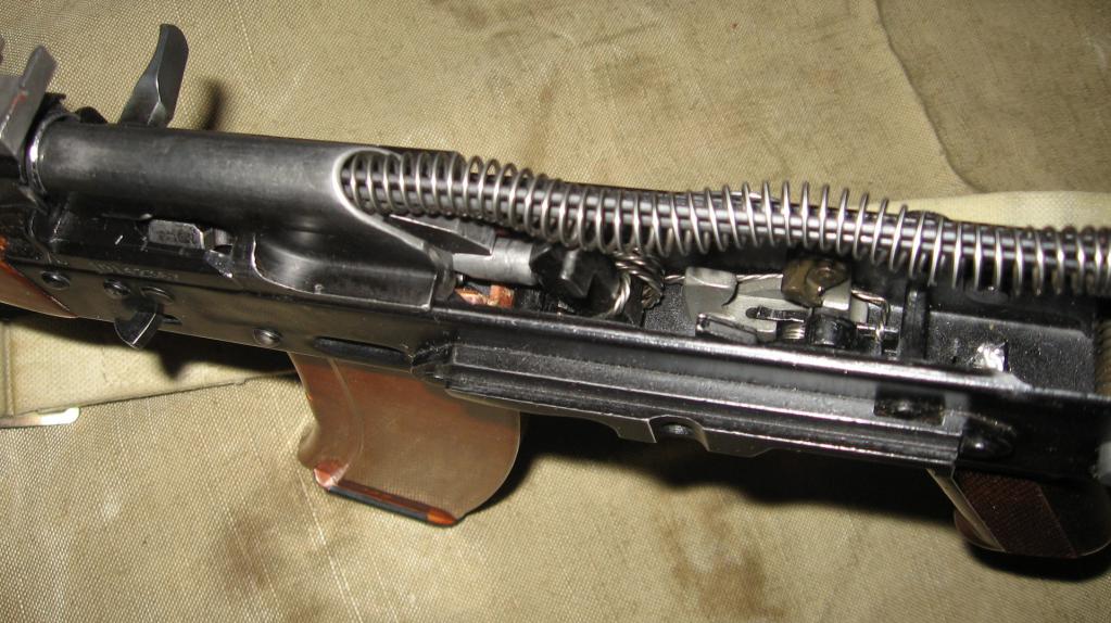
About purpose
USM AK-74 performs following features:
- Removes the trigger from the self-timer or cocking.
- Keeps the trigger cocked.
- Provides automatic or single shooting. Also, the trigger mechanism is responsible for the ceasefire.
- With the help of the USM in the AK-74, the drummer is affected.
- Prevents firing if the bolt is not locked.
- Sets an automatic weapon to safety.

About the Kalasha trigger
The impact on the drummer is carried out by means of a spring-loaded trigger. It can be armed and self-timer. Equipped with rectangular ledges, shank, trunnions and holes, which are equipped with the USM AK-74 axle. The trigger is actuated by a mainspring, which is attached to the trunnions and is made in the form of a loop. The second end of the spring is connected to the rectangular ledges on the trigger.
About the trigger retarder
In order to improve the accuracy of the battle during automatic firing, the trigger is slowed down by a special spring-loaded element in the USM AK-74 device, which is called the retarder. It is equipped with a front and rear lugs, a hole for the axle, a spring and a latch that is studded to the rear lugs.

About single shooting
After a shot has been fired, the trigger is moved to the rear position and held with a sear. This element is located on the same axis as the trigger. The sear is equipped with a special cutout for the interpreter sector, a spring and an axial hole. If the interpreter is on safety, its turns are limited due to the cutout.
How is burst firing done?
The trigger is removed from the platoon thanks to the spring-loaded self-timer. With the help of this USM element, trigger release is prevented if the barrel channel of the machine gun is not closed or the shutter is not locked. The self-timer is equipped with:
- A sear with which the trigger is set to the platoon.
- A special lever that rotates the self-timer by a ledge in the bolt carrier when it is in the forward position.
- Spring. It is located on the same axis as the self-timer. The long end of the spring crosses the receiver and winds up in an annular groove on the axles where the self-timer and trigger are located.
About translator
With the help of this element of the trigger mechanism, the machine is set to perform firing in single and bursts. The translator is equipped with special trunnions. Their location was special holes in the receiver. If the translator is in the lower position, the Kalashnikov assault rifle is set to fire single shots. In the middle position - automatic fire. If the translator is moved all the way up, then the AK is set to safety.

Causes of misfires
During the use of the Kalashnikov assault rifle, misfires sometimes occur. In this case, the ammunition is sent to the chamber, the shutter is shifted to the forward position, and after the trigger is released, the shot is not fired. There can be several reasons for misfires. Most likely the cartridge is faulty. Also, the drummer, which is wedged in the bolt, or the trigger mechanism may be faulty. According to experts, misfires occur when the mechanical assembly is dirty or the lubricant has frozen in it. In this case, the machine is recharged. If the delay is repeated again, then disassembling the USM AK-74 can correct the situation. This unit may be broken or completely worn out.
How to remove the mechanical trigger assembly?
Judging by the reviews, some owners of carbines are interested in how to remove the trigger on the AK-74. Disassembly of automatic weapons is carried out as follows:
- First you need to disconnect the clip from the machine. To do this, hold the weapon with one hand by the forearm, grab the magazine with the other and, while pressing the locking latch, gently pull down. The locking bar is equipped with special protrusions that are pressed in with an awl or screwdriver.
- There is a ramrod in a special hole under the barrel of the carbine. It needs to be removed.
- Then the cover is removed from the receiver. The guide tube in the return mechanism is equipped with a small protrusion. To dismantle, you need to press on it, and lift the cover itself.
- After that, you can proceed to extract the shock-return mechanism. This will be easy if his tube is moved forward until its heel goes beyond the longitudinal groove of the box. To get the tube, you need to pry it by the end.
- Detach the shutter frame. The weapon is pre-set for automatic firing. The dismantling of the bolt carrier consists in pulling it all the way, lifting it up and moving it back.
- To remove the shutter, you need to take it back and turn it. If the actions are performed correctly, a protrusion should appear in the groove of the bolt carrier. After that, the shutter is advanced forward and removed. With the help of a special punch, a pin is knocked out, which is necessary to hold the striker on the axis in the ejector, which is also dismantled along with the drummers.
- Before dismantling the gas pipe, the flag that closes it must be set in a vertical position. One end of the tube is connected to the branch pipe. To detach it, you need to pry it over the edge.
How to disassemble trigger in a carbine?
After dismantling the trigger mechanism, you can proceed to disassemble it. Start by separating the trigger. To remove it, you need to press on a special lever in the self-timer.

With the help of any pointed object, the mainspring rises from both edges and winds up with both ends behind the protrusions of the trigger, the axis of which must be shifted to the left. It then rotates until its trunnion is turned towards the chamber. After that, the trigger and the mainspring are removed. After completing these steps, with the help of a punch, they begin to dismantle the trigger and sear. When removing the axis previously shifted to the left, the sear is held in the single firing mode. The self-timer (AC) is also dismantled with a punch, the axis of which, as in the previous case, is shifted to the left before removal. In the course of work, it is necessary to hold the AC and its spring. In the machine for clips with ammunition there is a special opening through which the self-timer is removed. You can start dismantling the translator after it is set perpendicular to the receiver. Before removal, the axis of this element is shifted to the right.