Springs and other elastic elements. The spring pitch is determined by dependence. Car suspension spring with variable stiffness
Recently, they have again begun to use long-known in technology, but little used stranded springs, consisting of several wires (cores) twisted into ropes (Fig. 902, I-V), from which springs are wound (compression, tension, torsion). The ends of the rope are scalded to avoid stranding. The lay angle δ (see Fig. 902, I) is usually made equal to 20-30 °.
The direction of the cable lay is chosen so that the cable twists rather than unwinds when the spring is elastically deformed. Compression springs with right windings are made from left lay ropes and vice versa. For tension springs, the direction of the lay and the inclination of the turns must match. In torsion springs, the direction of the lay is indifferent.
The lay density, lay pitch and lay technology have a great influence on the elastic properties of stranded springs. After the rope is twisted, elastic recoil occurs, the cores move away from each other. The winding of the springs, in turn, changes the mutual arrangement of the cores of the coils.

In the free state of the spring, there is almost always a gap between the cores. In the initial stages of loading, the springs work as separate wires; its characteristic (Fig. 903) has a gentle appearance.
With a further increase in loads, the cable twists, the cores close and begin to work as one; spring stiffness increases. For this reason, the characteristics of stranded springs have a breaking point (a) corresponding to the beginning of the closing of the coils.

The advantage of stranded springs is due to the following. The use of several thin wires instead of one massive one makes it possible to increase the calculated stresses due to the increased strength inherent in thin wires. A coil composed of strands of small diameter is more pliable than an equivalent massive coil, partly due to increased allowable stresses, and mainly due to a higher value for each individual strand of the index c = D / d, which sharply affects the stiffness.
The flat characteristic of stranded springs can be useful in a number of cases when it is required to obtain large elastic deformations in limited axial and radial dimensions.
Another distinguishing feature of stranded springs is increased damping capacity due to friction between coils during elastic deformation. Therefore, such springs can be used to dissipate energy, with shock-like loads, to dampen vibrations that occur under such loads; they also contribute to the self-damping of the resonant oscillations of the coils of the spring.
However, increased friction causes wear on the coils, accompanied by a decrease in spring fatigue resistance.
In a comparative assessment of the flexibility of stranded springs and single-wire springs, a mistake is often made by comparing springs with the same cross-sectional area (total for stranded) coils.
This does not take into account the fact that the load capacity of stranded springs, other things being equal, is less than that of single-wire springs, and it decreases with an increase in the number of cores.
The assessment should be based on the condition of equal load capacity. Only in this case it is correct with a different number of cores. In this assessment, the benefits of stranded springs appear to be more modest than might be expected.
Let us compare the compliance of stranded springs and a single-wire spring with the same average diameter, number of turns, force (load) P and safety margin.
As a first approximation, we will consider a stranded spring as a series of parallel springs with coils of small cross section.
The diameter d" of the core of a stranded spring under these conditions is related to the diameter d of the massive wire by the ratio

where n is the number of cores; [τ] and [τ"] are allowable shear stresses; k and k" are spring shape factors (their index).
Due to the closeness of the values  to unity can be written

The ratio of the masses of the compared springs

or by substituting the value d "/d from equation (418)
The values of the ratios d "/d and m" / m, depending on the number of cores, are given below.
As can be seen, the decrease in the wire diameter for stranded springs is not at all so large as to give a significant gain in strength even in the range of small values of d and d" (by the way, this circumstance justifies the above assumption that the factor is close to unity.
The ratio of the strain λ" of a stranded spring to the strain λ of a solid wire spring
![]()
Substituting d "/d from equation (417) into this expression, we obtain
![]()
The value of [τ"]/[τ], as indicated above, is close to unity. Therefore
![]()
The values of λ"/λ calculated from this expression for a different number of strands n are given below (when determining, the initial value k = 6 was taken for k).
As can be seen, under the initial assumption of equality of the load, the transition to stranded springs provides, for real values of the number of strands, a gain in compliance of 35–125%.
On fig. 904 shows a summary diagram of the change in the factors d "/d; λ" / λ and m "/m for equally loaded and equal strength stranded springs depending on the number of cores.

Along with an increase in mass with an increase in the number of strands, an increase in the diameter of the cross section of the turns should be taken into account. For the number of strands within n = 2–7, the cross-sectional diameter of the turns is, on average, 60% larger than the diameter of an equivalent whole wire. This leads to the fact that in order to maintain the clearance between the coils, it is necessary to increase the pitch and the total length of the springs.
The yield gain provided by multi-strand springs can be obtained in a single-wire spring. To do this, simultaneously increase the diameter D of the spring; reduce the diameter d of the wire; increase the level of stresses (i.e., high-quality steels are used). Ultimately, an equal-volume single-wire spring will be lighter, smaller, and much cheaper than a multi-strand spring due to the complexity of manufacturing multi-strand springs. To this we can add the following disadvantages of stranded springs:
1) the impossibility (for compression springs) of correct filling of the ends (by grinding the ends of the spring), which ensures the central application of the load; there is always some eccentricity of the load, causing additional bending of the spring;
2) manufacturing complexity;
3) dispersion of characteristics for technological reasons; difficulty in obtaining stable and reproducible results;
4) wear of the cores as a result of friction between the coils, which occurs with repeated deformations of the springs and causes a sharp drop in the fatigue resistance of the springs. The last disadvantage excludes the use of stranded springs for long-term cyclic loading.
Stranded springs are applicable for static loading and periodic dynamic loading with a limited number of cycles.
Definition
The force that occurs as a result of the deformation of the body and trying to return it to its original state is called elastic force.
Most often it is denoted by $(\overline(F))_(upr)$. The elastic force appears only when the body is deformed and disappears if the deformation disappears. If, after removing the external load, the body completely restores its size and shape, then such a deformation is called elastic.
R. Hooke, a contemporary of I. Newton, established the dependence of the elastic force on the magnitude of the deformation. Hooke doubted the validity of his conclusions for a long time. In one of his books, he gave an encrypted formulation of his law. Which meant: "Ut tensio, sic vis" in Latin: what is the stretch, such is the strength.
Consider a spring subject to a tensile force ($\overline(F)$) that is directed vertically downwards (Fig. 1).
The force $\overline(F\ )$ is called the deforming force. Under the influence of a deforming force, the length of the spring increases. As a result, an elastic force ($(\overline(F))_u$) appears in the spring, balancing the force $\overline(F\ )$. If the deformation is small and elastic, then the elongation of the spring ($\Delta l$) is directly proportional to the deforming force:
\[\overline(F)=k\Delta l\left(1\right),\]
where in the coefficient of proportionality is called the stiffness of the spring (coefficient of elasticity) $k$.
Rigidity (as a property) is a characteristic of the elastic properties of a body that is being deformed. Rigidity is considered the ability of a body to resist an external force, the ability to maintain its geometric parameters. The greater the stiffness of the spring, the less it changes its length under the influence of a given force. The stiffness coefficient is the main characteristic of stiffness (as a property of a body).
The coefficient of spring stiffness depends on the material from which the spring is made and its geometric characteristics. For example, the stiffness coefficient of a coiled coil spring, which is wound from round wire and subjected to elastic deformation along its axis, can be calculated as:
where $G$ is the shear modulus (value depending on the material); $d$ - wire diameter; $d_p$ - spring coil diameter; $n$ is the number of coils of the spring.
The unit of measure for the stiffness coefficient in the International System of Units (SI) is the newton divided by the meter:
\[\left=\left[\frac(F_(upr\ ))(x)\right]=\frac(\left)(\left)=\frac(H)(m).\]
The stiffness coefficient is equal to the amount of force that must be applied to the spring to change its length per unit distance.
Spring stiffness formula
Let $N$ springs be connected in series. Then the stiffness of the entire joint is equal to:
\[\frac(1)(k)=\frac(1)(k_1)+\frac(1)(k_2)+\dots =\sum\limits^N_(\ i=1)(\frac(1) (k_i)\left(3\right),)\]
where $k_i$ is the stiffness of the $i-th$ spring.
When the springs are connected in series, the stiffness of the system is determined as:
Examples of problems with a solution
Example 1
Exercise. The spring in the absence of load has a length $l=0.01$ m and a stiffness equal to 10 $\frac(N)(m).\ $What will be the stiffness of the spring and its length if the force acting on the spring is $F$= 2 N ? Assume that the deformation of the spring is small and elastic.

Solution. The stiffness of the spring under elastic deformations is a constant value, which means that in our problem:
Under elastic deformations, Hooke's law is fulfilled:
From (1.2) we find the elongation of the spring:
\[\Delta l=\frac(F)(k)\left(1.3\right).\]
The length of the stretched spring is:
Calculate the new length of the spring:
Answer. 1) $k"=10\ \frac(Н)(m)$; 2) $l"=0.21$ m
Example 2
Exercise. Two springs with stiffnesses $k_1$ and $k_2$ are connected in series. What will be the elongation of the first spring (Fig. 3) if the length of the second spring is increased by $\Delta l_2$?

Solution. If the springs are connected in series, then the deforming force ($\overline(F)$) acting on each of the springs is the same, that is, it can be written for the first spring:
For the second spring we write:
If the left parts of expressions (2.1) and (2.2) are equal, then the right parts can also be equated:
From equality (2.3) we obtain the elongation of the first spring:
\[\Delta l_1=\frac(k_2\Delta l_2)(k_1).\]
Answer.$\Delta l_1=\frac(k_2\Delta l_2)(k_1)$
 SPRINGS AND ELASTIC ELEMENTS n n n 1. General characteristics of springs Springs are widely used in structures as vibration isolating, shock-absorbing, reciprocating, tensioning, dynamometric and other devices. Spring types. According to the type of perceived external load, tension, compression, torsion and bending springs are distinguished.

 SPRINGS AND ELASTIC ELEMENTS n n twisted springs (cylindrical - extensions, Fig. 1 a, compressions, Fig. 1 b; torsion, Fig. 1 c, shaped-compressions, Fig. 1 d-e), special springs (dial-shaped and ring, Fig. 2 a and b, - compression; true and springs, Fig. 2 c, - bending; spiral, Fig. 2 d - torsion, etc.) The most common are twisted cylindrical springs made of round wire.
 SPRINGS AND ELASTIC ELEMENTS n Tension springs (see Fig. 1 a) are wound, as a rule, without gaps between the coils, and in most cases with an initial tension (pressure) between the coils, which partially compensates for the external load. The tension is usually (0.25 - 0.3) Fpr (Fnp is the limiting tensile force at which the elastic properties of the spring material are completely exhausted).
 SPRINGS AND ELASTIC ELEMENTS n n To transfer an external load, such springs are provided with hooks. For example, for springs of small diameter (3-4 mm), the hooks are made in the form of bent last turns (Fig. 3 a-c). However, such hooks reduce the resistance of fatigue springs due to the high concentration of stresses in the places of bending. For critical springs with a diameter of more than 4 mm, embedded hooks are often used (Fig. 3d-e), although they are less technologically advanced.
 SPRINGS AND ELASTIC ELEMENTS n n n Compression springs (see Fig. 1 b) are coiled with a gap between the coils, which should be 10-20% higher than the axial elastic displacements of each coil at the highest external load. The support planes of the springs are obtained by pressing the last turns to the neighboring ones and grinding them perpendicular to the axis. Long springs under load can lose stability (bulge). To prevent buckling, such springs are usually placed on special mandrels (Fig. 4 a) or in glasses (Fig. 4 b).


 SPRINGS AND ELASTIC ELEMENTS n n n Coaxiality of springs with mating parts is achieved by installing support coils in special plates, bores in the body, grooves (see Fig. 4 c). Torsion springs (see Fig. 1 c) are usually wound with a small angle of rise and small gaps between the coils (0.5 mm). They perceive the external load with the help of hooks formed by the bending of the end turns.
 SPRINGS AND ELASTIC ELEMENTS n n Basic parameters of coiled springs. Springs are characterized by the following main parameters (see Fig. 1b): wire diameter d or cross-sectional dimensions; average diameter Do, index c = Do/d; the number n of working turns; length Ho of the working part; step t = Ho/n turns, angle = arctg turns rise. The last three parameters are considered in the unloaded and loaded states.
 SPRINGS AND ELASTIC ELEMENTS n n The spring index characterizes the curvature of the coil. Springs with an index of 3 are not recommended due to the high stress concentration in the coils. Usually, the spring index is chosen depending on the wire diameter as follows: for d 2.5 mm, d = 3--5; 6-12 mm respectively c = 5-12; 4-10; 4-9.
 SPRINGS AND ELASTIC ELEMENTS n n Materials. Coiled springs are made by cold or hot winding followed by end finishing, heat treatment and control. The main materials for springs are - high-strength special spring wire of 1, II and III classes with a diameter of 0.2-5 mm, as well as steels: high-carbon 65, 70; manganese 65 G; siliceous 60 C 2 A, chrome vanadium 50 HFA, etc.
 SPRINGS AND ELASTIC ELEMENTS n n Springs designed to work in a chemically active environment are made of non-ferrous alloys. To protect the surfaces of the coils from oxidation, critical springs are varnished or oiled, and especially critical springs are oxidized and zinc or cadmium coated on them.
 SPRINGS AND ELASTIC ELEMENTS n n 2. Calculation and design of twisted cylindrical springs Stresses in sections and displacements of coils. Under the action of the axial force F (Fig. 5 a) in the cross section of the coil of the spring, the resulting internal force F arises, parallel to the axis of the spring, and the moment T \u003d F D 0/2, the plane of which coincides with the plane of the pair of forces F. The normal cross section of the coil is inclined to plane moment per angle.

 SPRINGS AND ELASTIC ELEMENTS n n Projecting force factors in the cross section of a loaded spring on the x, y and z axes (Fig. 5, b), associated with the normal section of the coil, force F and moment T, we obtain Fx = F cos ; Fn = F sin (1) T = Mz = 0.5 F D 0 cos ; Mx = 0.5 F D 0 sin ;
 SPRINGS AND ELEMENTS n n n The angle of elevation of the turns is small (usually 12). Therefore, we can assume that the cross section of the spring works on torsion, neglecting other force factors. In the section of the coil, the maximum shear stress is (2) where Wk is the moment of resistance to torsion of the section of the coil
 SPRINGS AND ELASTIC ELEMENTS n Taking into account the curvature of the coils and relation (2), we write the equation (1), (3) n where F is the external load (tensile or compressive); D 0 is the average diameter of the spring; k - coefficient taking into account the curvature of the turns and the shape of the section (correction to the formula for torsion of a straight bar); k - allowable punitive stress during torsion.
 SPRINGS AND ELASTIC ELEMENTS n The value of the coefficient k for round wire springs with index c 4 can be calculated by the formula
 SPRINGS AND ELASTIC ELEMENTS n n If we take into account that for a wire of circular cross section Wk = d 3 / 16, then (4) A spring with a lift angle of 12 has an axial displacement n F, (5)
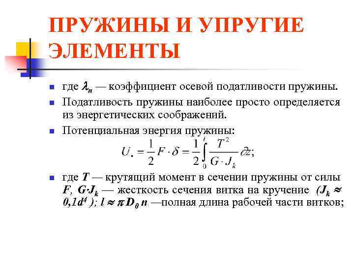 SPRINGS AND ELASTIC ELEMENTS n n where n is the coefficient of axial compliance of the spring. The compliance of a spring is most simply determined from energy considerations. Potential energy of the spring: where T is the torque in the cross section of the spring from the force F, G Jk is the torsional stiffness of the section of the coil (Jk 0, 1 d 4); l D 0 n is the total length of the working part of the coils;

 SPRINGS AND ELASTIC ELEMENTS n and coefficient of axial compliance of the spring (7) n where is the axial compliance of one coil (settlement in millimeters under the action of force F = 1 H),
 SPRINGS AND ELASTIC ELEMENTS n determined by the formula (8) n where G = E/ 0.384 E is the shear modulus (E is the modulus of elasticity of the spring material).
 SPRINGS AND ELASTIC ELEMENTS n From formula (7) it follows that the coefficient of compliance of the spring increases with an increase in the number of turns (length of the spring), its index (outer diameter) and a decrease in the shear modulus of the material.
 SPRINGS AND ELASTIC ELEMENTS n n Calculation and design of springs. The calculation of the wire diameter is carried out from the strength condition (4). For a given value of the index with (9) n where F 2 - the largest external load.
 SPRINGS AND ELASTIC ELEMENTS n Permissible stresses [k] for springs made of steels 60 C 2, 60 C 2 H 2 A and 50 HFA take: 750 MPa - under the action of static or slowly changing variable loads, as well as for non-critical springs; 400 MPa - for responsible dynamically loaded springs. For dynamically loaded responsible springs made of bronze [k] assign (0, 2-0, 3) in; for irresponsible bronze springs - (0.4-0.6) c.
 SPRINGS AND ELASTIC ELEMENTS n n The required number of working turns is determined from relation (5) according to the given elastic displacement (stroke) of the spring. If the compression spring is installed with a preliminary tightening (load) F 1, then (10) Depending on the purpose of the spring, the force F 1 = (0.1- 0.5) F 2. By changing the value of F 1, you can adjust the working draft of the spring. The number of turns is rounded up to half a turn for n 20 and to one turn for n > 20.
 SPRINGS AND ELASTIC ELEMENTS n Total number of turns n n H 0 \u003d H 3 + n (t - d), (12) where H 3 \u003d (n 1 - 0, 5) d is the length of the spring, compressed until adjacent working turns come into contact; t is the step of the spring. n n n 1 = n + (l, 5 -2, 0). (11) An additional 1, 5-2 turns are used for compression to create bearing surfaces for the spring. On fig. 6 shows the relationship between load and compression spring settling. Full length of unloaded spring n

 SPRINGS AND ELEMENTS n n The total number of turns is reduced by 0.5 due to the grinding of each end of the spring by 0.25 d to form a flat support end. The maximum spring settlement, i.e., the movement of the end of the spring until the coils are in full contact (see Fig. 6), is determined by the formula
 SPRINGS AND ELASTIC ELEMENTS n n n The pitch of the spring is determined depending on the value of 3 from the following approximate relationship: The length of the wire required for the manufacture of the spring where = 6 - 9° is the angle of elevation of the coils of an unloaded spring.
 SPRINGS AND ELASTIC ELEMENTS n n To prevent spring buckling from loss of stability, its flexibility H 0 / D 0 must be less than 2.5. .
 SPRINGS AND ELASTIC ELEMENTS n n n The installation length of the spring, i.e. the length of the spring after tightening it with force F 1 (see Fig. 6), is determined by the formula H 1 \u003d H 0 - 1 \u003d H 0 - n F 1 under the action of the largest external load spring length H 2 \u003d H 0 - 1 \u003d H 0 - n F 2 and the smallest length of the spring will be at force F 3 corresponding to the length H 3 \u003d H 0 - 3
 SPRINGS AND ELASTIC ELEMENTS n The angle of inclination of the straight line F = f() to the abscissa axis (see Fig. 6) is determined from the formula
 SPRINGS AND ELASTIC ELEMENTS n For heavy loads and cramped dimensions, composite compression springs are used (see Fig. 4, c) - a set of several (more often two) concentrically located springs that simultaneously perceive an external load. To prevent strong twisting of the end supports and distortions, the coaxial springs are wound in opposite directions (left and right). The supports are made in such a way that the mutual centering of the springs is ensured.
 SPRINGS AND ELASTIC ELEMENTS n n For uniform distribution of the load between them, it is desirable that the composite springs have the same drafts (axial displacements), and the lengths of the springs, compressed until the coils touch, would be approximately the same. In the unloaded state, the length of the extension springs H 0 = n d+2 hz; where hz \u003d (0, 5- 1, 0) D 0 is the height of one hook. At maximum external load, the length of the extension spring H 2 \u003d H 0 + n (F 2 - F 1 *) where F 1 * is the force of the initial compression of the coils during winding.
 SPRINGS AND ELASTIC ELEMENTS n n The length of the wire for the manufacture of the spring is determined by the formula where lz is the length of the wire for one trailer.
 SPRINGS AND ELASTIC ELEMENTS n Springs are common, in which instead of wire a cable is used, twisted from two to six wires of small diameter (d \u003d 0.8 - 2.0 mm), - stranded springs. By design, such springs are equivalent to concentric springs. Due to their high damping capacity (due to friction between the strands) and compliance, stranded springs work well in shock absorbers and similar devices. Under the action of variable loads, stranded springs quickly fail due to wear of the cores.
 SPRINGS AND ELASTIC ELEMENTS n In structures operating under vibration and shock loads, shaped springs are sometimes used (see Fig. 1, d-f) with a non-linear relationship between the external force and the elastic displacement of the spring.
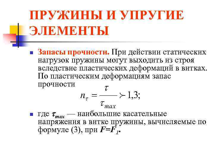 SPRINGS AND ELASTIC ELEMENTS n n Safety margins. Under the action of static loads, the springs can fail due to plastic deformations in the coils. In terms of plastic deformations, the margin of safety is where max is the largest shear stresses in the coil of the spring, calculated by formula (3), at F=F 1.
 SPRINGS AND ELASTIC ELEMENTS n Springs operating continuously under variable loads must be designed for fatigue resistance. Springs are characterized by asymmetric loading, in which the forces change from F 1 to F 2 (see Fig. 6). At the same time, in the sections of the turns of the voltage
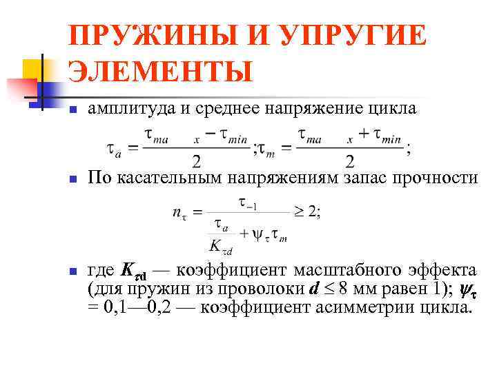 SPRINGS AND ELASTIC ELEMENTS n amplitude and average cycle stress n For tangential stresses safety margin n where K d is the scale effect coefficient (for springs made of wire d 8 mm is equal to 1); = 0, 1- 0, 2 - cycle asymmetry coefficient.
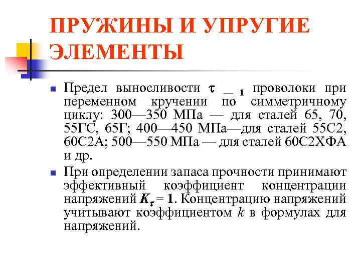 SPRINGS AND ELASTIC ELEMENTS n n Endurance limit - 1 wire with variable torsion in a symmetrical cycle: 300-350 MPa - for steels 65, 70, 55 GS, 65 G; 400-450 MPa - for steels 55 C 2, 60 C 2 A; 500-550 MPa - for steels 60 C 2 HFA, etc. When determining the safety factor, the effective stress concentration factor K = 1 is taken. The stress concentration is taken into account by the coefficient k in the formulas for stresses.
 SPRINGS AND ELASTIC ELEMENTS n In the case of resonant vibrations of springs (for example, valve springs), an increase in the variable component of the cycle can occur with m unchanged. In this case, the margin of safety for alternating stresses
 SPRINGS AND ELASTIC ELEMENTS n To increase fatigue resistance (by 20-50%), the springs are strengthened by shot-blasting, which creates compressive residual stresses in the surface layers of the coils. For processing springs, balls with a diameter of 0.5-1.0 mm are used. More efficient is the treatment of springs with balls of small diameters at high flight speeds.
 SPRINGS AND ELASTIC ELEMENTS n n Impact load calculation. In a number of designs (shock absorbers, etc.), the springs operate under shock loads applied almost instantly (at high speed) with a known impact energy. In this case, the individual coils of the spring gain considerable speed and can collide dangerously. The calculation of real systems for shock loading is associated with significant difficulties (taking into account contact, elastic and plastic deformations, wave processes, etc.); therefore, for an engineering application, we restrict ourselves to the energy calculation method.
 SPRINGS AND ELASTIC ELEMENTS n n n The main task of impact load analysis is to determine the dynamic settlement (axial displacement) and static load equivalent to the impact on a spring with known dimensions. Consider the impact of a rod with mass m on a spring damper (Fig. 7). If we neglect the deformation of the piston and assume that after the impact, elastic deformations instantly cover the entire spring, we can write the energy balance equation in the form where Fd is the force of gravity of the rod; K is the kinetic energy of the system after the collision,
 SPRINGS AND ELASTIC ELEMENTS n determined by the formula (13) n where v 0 - piston speed; - the coefficient of reduction of the mass of the spring to the place of impact
 SPRINGS AND ELASTIC ELEMENTS n n n If we assume that the speed of movement of the coils of the spring changes linearly along its length, then = 1/3. The second term on the left side of equation (13) expresses the work of the piston after impact with dynamic spring settlement q. The right side of equation (13) is the potential energy of the deformation of the spring (with compliance m), which can be returned by gradually unloading the deformed spring.


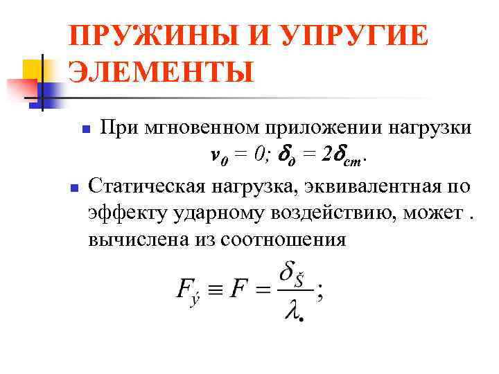 SPRINGS AND ELASTIC ELEMENTS With an instantaneous load v 0 = 0; d \u003d 2 tbsp. A static load equivalent in effect to an impact can. calculated from the relation n n
 SPRINGS AND ELASTIC ELEMENTS n n Rubber elastic elements are used in the construction of elastic couplings, vibration and noise insulating supports and other devices to obtain large displacements. Such elements usually transfer the load through metal parts (plates, tubes, etc.).
 SPRINGS AND ELASTIC ELEMENTS n Advantages of rubber elastic elements: electrical insulating ability; high damping capacity (energy dissipation in rubber reaches 30-80%); the ability to store more energy per unit mass than spring steel (up to 10 times). In table. 1 shows calculation schemes and formulas for the approximate determination of stresses and displacements for rubber elastic elements.
 SPRINGS AND ELASTIC ELEMENTS n n The material of the elements is technical rubber with a tensile strength (8 MPa; shear modulus G = 500-900 MPa. In recent years, pneumoelastic elastic elements have become widespread.
The elastic properties of the spring suspension are evaluated using the power characteristics and the stiffness coefficient or the coefficient of flexibility (flexibility). In addition, springs and springs are characterized by geometric dimensions. The main dimensions (Fig. 1) include: the height of the spring or spring in a free state without load H s and the height under load H gr, the length of the spring, the diameter of the spring, the diameter of the rod, the number of working coils of the spring. The difference between H sv and H gr is called spring deflection (springs)f. The deflection obtained from a load lying quietly on the spring is called static. For leaf springs, for more convenient measurement, the deflection is determined by the dimensions H St and H gr near the clamp. Flexible properties of springs (springs) determined by one of two quantities:
- flexibility factor(or just flexibility);
- stiffness factor(or just hardness).
Rice. 1 - Main dimensions of springs and springs
The deflection of a spring (spring) under the action of a force equal to unity is called flexibility f 0:
where P is the external force acting on the spring, N;
f - spring deflection, m.
An important characteristic of a spring is its rigidity. and, which is numerically equal to the force that causes deflection equal to one. In this way,
and= P/f.
For springs whose deflection is proportional to the load, the equality
P= and f.
Rigidity- the reciprocal of flexibility. Flexibility and stiffness of springs (springs) depend on their main dimensions. With an increase in the length of the spring or with a decrease in the number and cross-section of sheets, its flexibility increases, and its rigidity decreases. For springs, with an increase in the average diameter of the turns and their number, and with a decrease in the cross section of the rod, the flexibility increases, and the rigidity decreases.
The magnitude of the stiffness and deflection of the spring or spring determines the linear relationship between its deflection and the elastic force P = and f, presented graphically in (Fig. 2). The diagram of the operation of a frictionless cylindrical spring (Fig. 2, a) is depicted by one straight line 0A, corresponding to both the loading of the spring (an increase in P) and its unloading (a decrease in P). Rigidity in this case is a constant value:
and= P/f∙tgα.
Springs of variable stiffness (aperiodic) without friction have a diagram in the form of a line 0AB (Fig. 2, b).

Rice. 2 - Diagrams of the operation of springs (a, b) and springs (c)
At leaf spring operation friction occurs between its sheets, which contributes to the damping of the vibrations of the sprung vehicle and creates a more relaxed movement. At the same time, too much friction, increasing the stiffness of the spring, degrades the suspension quality. The nature of the change in the elastic force of the spring under static loading is shown in (Fig. 2, c). This relationship is a closed curved line, the upper branch of which 0A 1 shows the relationship between the load and the deflection of the spring when it is loaded, and the lower A 1 A 2 0 - when unloaded. The difference between the branches characterizing the change in the elastic forces of the spring when it is loaded and unloaded is due to friction forces. The area bounded by the branches is equal to the work expended on overcoming the friction forces between the leaf springs. When loaded, the friction forces seem to resist the increase in deflection, and when unloaded, they prevent the spring from straightening. In wagon springs, the friction force increases in proportion to the deflection, since the forces of pressing the sheets against each other increase accordingly. The amount of friction in the spring is usually estimated by the so-called coefficient of relative friction φ, equal to the ratio of the friction force Rtr to the force P that creates the elastic deformation of the spring:
The magnitude of the friction force is related to the deflection f and the stiffness of the spring and, due to its elastic properties, dependence
They are formed by protrusions on the shaft, which are included in the mating grooves of the wheel hub. Both in appearance and in terms of dynamic operating conditions, splines can be considered multi-key connections. Some authors call them serrations.
 Basically, straight-sided splines are used (a), involute (b) GOST 6033-57 and triangular (c) spline profiles are less common.
Straight-sided splines can center the wheel along the side surfaces (a), along the outer surfaces (b), along the inner surfaces (c).
Compared to splines, splines:
Have a large bearing capacity;
Better center the wheel on the shaft;
Strengthen the shaft section due to the greater moment of inertia of the ribbed section compared to the round one;
` require special equipment for making holes.
The main criteria for the performance of slots are:
è resistance of side surfaces to crushing (calculation is similar to dowels);
è wear resistance during fretting corrosion (small mutual vibrational movements).
Crushing and wear are associated with one parameter - contact stress (pressure) s cm . This allows splines to be calculated according to the generalized criterion for both crushing and contact wear. Permissible stresses [ s]cm assigned on the basis of operating experience of similar structures.
For the calculation, the uneven distribution of the load over the teeth is taken into account,
where Z - number of slots h – working height of slots, l - working length of the slots, d cf - the average diameter of the spline connection. For involute splines, the working height is taken equal to the profile modulus, for d cf take the pitch diameter.
Symbols of a straight-sided spline connection are made up of the designation of the centering surface D , d or b , number of teeth Z , nominal sizes d x D (as well as the designation of tolerance fields for the centering diameter and on the sides of the teeth). For example, D 8 x 36H7/g6 x 40 means eight-spline connection centered on the outer diameter with dimensions d = 36 and D =40 mm and fit on the centering diameter H7/g6 .
TEST QUESTIONS
s What is the difference between detachable and non-detachable connections?
s Where and when are welded joints used?
s What are the advantages and disadvantages of welded joints?
s What are the main groups of welded joints?
s How do the main types of welds differ?
s What are the advantages and disadvantages of riveted joints?
s Where and when are riveted joints used?
s What are the criteria for strength analysis of rivets?
s What is the design principle of threaded connections?
s What are the applications for the main thread types?
s What are the advantages and disadvantages of threaded connections?
s Why is it necessary to lock threaded connections?
s What designs are used to lock threaded connections?
s How is the ductility of parts taken into account when calculating a threaded connection?
s What thread diameter is found from the strength calculation?
s What is the thread diameter to indicate the thread?
s What is the design and main purpose of pin connections?
s What are the load types and design criteria for pins?
s What is the design and main purpose of keyed connections?
s What are the load types and design criteria for keys?
s What is the design and main purpose of splines?
What are the types of loading and criteria for calculating splines
SPRINGS. ELASTIC ELEMENTS IN MACHINES
Each car has specific details that are fundamentally different from all the others. They are called elastic elements. Elastic elements have a variety of designs that are very different from each other. Therefore, a general definition can be given.
Elastic elements are parts whose rigidity is much less than the rest, and the deformations are higher.
Due to this property, elastic elements are the first to perceive shocks, vibrations, and deformations.
Most often, elastic elements are easy to detect when inspecting the machine, such as rubber tires, springs and springs, soft seats for drivers and drivers.
Sometimes the elastic element is hidden under the guise of another part, for example, a thin torsion shaft, a stud with a long thin neck, a thin-walled rod, a gasket, a shell, etc. However, here, too, an experienced designer will be able to recognize and use such a "disguised" elastic element precisely by its relatively low rigidity.
On the railway, due to the severity of the transport, the deformation of the track parts is quite large. Here, the elastic elements, along with the springs of the rolling stock, actually become rails, sleepers (especially wooden, not concrete) and the soil of the track embankment.
Elastic elements are widely used:
è for shock absorption (reduction of accelerations and inertial forces during shock and vibration due to a significantly longer deformation time of the elastic element compared to rigid parts);
è to create constant forces (for example, elastic and slotted washers under the nut create a constant friction force in the threads, which prevents self-unscrewing);
è for forceful closing of mechanisms (to eliminate unwanted gaps);
è for the accumulation (accumulation) of mechanical energy (clock springs, the spring of a weapon striker, the arc of a bow, the rubber of a slingshot, a ruler bent near a student's forehead, etc.);
è for measuring forces (spring balances are based on the relationship between weight and strain of the measuring spring according to Hooke's law).
Typically, elastic elements are made in the form of springs of various designs.
The main distribution in machines are elastic compression and extension springs. In these springs, the coils are subject to torsion. The cylindrical shape of the springs is convenient for placing them in machines.
The main characteristic of a spring, like any elastic element, is stiffness or its inverse compliance. Rigidity K determined by the dependence of the elastic force F from deformation x . If this dependence can be considered linear, as in Hooke's law, then the stiffness is found by dividing the force by the deformation K =f/x .
If the dependence is non-linear, as is the case in real structures, the stiffness is found as the derivative of the force with respect to deformation K =∂ f/ ∂ x.
Obviously, here you need to know the type of function F =f (x ) .
For large loads, if it is necessary to dissipate the energy of vibration and shock, packages of elastic elements (springs) are used.
The idea is that when the composite or layered springs (springs) are deformed, the energy is dissipated due to the mutual friction of the elements.
A package of disc springs is used to absorb shocks and vibrations in the inter-bogie elastic coupling of electric locomotives ChS4 and ChS4 T.
In the development of this idea, at the initiative of the employees of our academy, disk springs (washers) are used in the bolted joints of the rail joints on the Kuibyshev Road. The springs are placed under the nuts before tightening and provide high constant friction forces in the connection, besides unloading the bolts.
Materials for elastic elements should have high elastic properties, and most importantly, not lose them over time.
The main materials for springs are high-carbon steels 65.70, manganese steels 65G, silicon steels 60S2A, chrome-vanadium steel 50HFA, etc. All of these materials have superior mechanical properties compared to conventional structural steels.
In 1967, at the Samara Aerospace University, a material was invented and patented, called metal rubber "MR". The material is made from crumpled, tangled metal wire, which is then pressed into the required shapes.
The colossal advantage of metal rubber is that it perfectly combines the strength of metal with the elasticity of rubber and, in addition, due to significant interwire friction, it dissipates (dampers) vibration energy, being a highly effective means of vibration protection.
The density of the entangled wire and the pressing force can be adjusted, obtaining the specified values of the stiffness and damping of the metal rubber in a very wide range.
Metal rubber undoubtedly has a promising future as a material for the manufacture of elastic elements.
Elastic elements require very precise calculations. In particular, they are necessarily counted on rigidity, since this is the main characteristic.
However, the designs of elastic elements are so diverse, and the calculation methods are so complex that it is impossible to bring them in any generalized formula. Especially within the framework of our course, which is over here.
TEST QUESTIONS
1. On what basis can elastic elements be found in the design of the machine?
2. For what tasks are elastic elements used?
3. What characteristic of the elastic element is considered the main one?
4. What materials should elastic elements be made of?
5. How are Belleville springs used on the Kuibyshev road?
| INTRODUCTION………………………………………………………………………………… | |
| 1. GENERAL QUESTIONS OF CALCULATION OF PARTS OF MACHINES……………………………………... | |
| 1.1. Rows of preferred numbers…………………………………………………... | |
| 1.2. The main criteria for the performance of machine parts…………………… 1.3. Calculation of fatigue resistance at alternating stresses……….. | |
| 1.3.1. Variable voltages……………………………………………….. 1.3.2. Endurance limits……………………………………………….. 1.4. Safety factors……………………………………………………. | |
| 2. MECHANICAL GEARS……………………………………………………………... 2.1. General information……………………………………………………………….. 2.2. Characteristics of drive gears…………………………………………….. | |
| 3. GEARS ………………………………………………………………….. 4.1. Working conditions of the teeth…………………………………………. 4.2. Materials of Gears………………………………………………………………………………………………………………………………………………………………………………………………………………………………………………………………………………………………………………………………4.3. Typical types of tooth destruction………………………………………… 4.4. Design load……………………………………………………………. 4.4.1. Design load factors…………………………………. 4.4.2. Accuracy of gears…………………………………………….. 4.5. Cylindrical gears……………………………………… | |
| 4.5.1. Forces in engagement………………………………………………………. 4.5.2. Calculation for contact fatigue resistance……………………. 4.5.3. Calculation for bending fatigue resistance……………………… 4.6. Bevel gears……………………………………………… 4.6.1. Main parameters…………………………………………………. 4.6.2. Forces in engagement………………………………………………………. 4.6.3. Calculation for contact fatigue resistance…………………… 4.6.4. Calculation of fatigue resistance in bending……………………. | |
| 5. WORM GEARS……………………………………………………………………. 5.1. General information……………………………………………………………….. 5.2. Forces in engagement………………………………………………………………. 5.3. Materials of worm gears……………………………………………… 5.4. Strength calculation…………………………………………………………….. | |
| 5.5. Thermal calculation…………………………………………………………………. 6. SHAFTS AND AXES………………………………………………………………………………. 6.1. General information……………………………………………………………….. 6.2. Estimated load and performance criterion………………………… 6.3. Design calculation of shafts…………………………………………………. 6.4. Calculation scheme and procedure for calculating the shaft……………………………………….. 6.5. Calculation for static strength………………………………………………. 6.6. Fatigue resistance calculation…………………………………………….. 6.7. Calculation of shafts for stiffness and vibration resistance…………………………… | |
| 7. ROLLING BEARINGS ………………………………………………………………… 7.1. Classification of rolling bearings………………………………………… 7.2. Designation of bearings according to GOST 3189-89……………………………… 7.3. Features of angular contact bearings……………………………… 7.4. Schemes of installation of bearings on shafts……………………………………… 7.5. Estimated load on angular contact bearings………………….. 7.6. Causes of failure and calculation criteria………………………........... 7.7. Materials of bearing parts……..……………………………………. 7.8. Selection of bearings according to static load capacity (GOST 18854-94)………………………………………………………………… | |
| 7.9. Selection of bearings according to dynamic load capacity (GOST 18855-94)……………………………………………………………… 7.9.1. Initial data……………………………………………………. 7.9.2. Basis for selection………………………………………………….. 7.9.3. Features of the selection of bearings……………………………….. | |
| 8. PLAIN BEARINGS…………………………………………………………. | |
| 8.1. General information …………………………………………………………….. | |
| 8.2. Operating conditions and friction modes …………………………………………… | |
| 7. CLUTCHES | |
| 7.1. Rigid Couplings | |
| 7.2. Compensating couplings | |
| 7.3. Movable couplings | |
| 7.4. Flexible couplings | |
| 7.5. Friction clutches | |
| 8. CONNECTIONS OF MACHINE PARTS | |
| 8.1. Permanent connections | |
| 8.1.1. Welded joints | |
| Calculation of the strength of welds | |
| 8.1.2. Rivet connections | |
| 8.2. Detachable connections | |
| 8.2.1. THREADED CONNECTIONS | |
| Calculation of the strength of threaded connections | |
| 8.2.2. Pin connections | |
| 8.2.3. Keyed connections | |
| 8.2.4. Spline connections | |
| 9. Springs…………………………………… |
| | | next lecture ==> | |