Important points in AMI BIOS setup. How to set up the BIOS to boot from a disk or flash drive
If you were looking for BIOS settings in pictures, then you have come to the right place.
The changes made will be protected by a lithium battery built into the motherboard and maintaining the required parameters in the event of a voltage loss.
Thanks to the program, it is possible to establish a stable interaction of the operating system (OS) with PC devices.
Attention! The present Boot network configuration section allows you to adjust parameters regarding system boot speed, keyboard and mouse settings.
After completing the work or familiarizing yourself with the Bios Setup Utility menu, you must press the burning Exit key, which automatically saves the changes made.
Section Main - Main menu
Let's start with the MAIN section, which is used to modify the settings and adjust the timing.
Here you can independently set the time and date of the computer, as well as configure the connected hard drives and other drives.

To reformat the working mode of the hard disk, you need to select the hard disk (for example: "SATA 1", as shown in the figure).
- type- this item indicates the type of connected hard disk;
- LBA Large Mode- Responsible for supporting drives larger than 504 MB. So the recommended value here is AUTO.
- Block (Multi-Sector Transfer) - For more fast work here we recommend choosing the AUTO mode;
- PIO Mode- Enables the hard drive to operate in legacy data exchange mode. It would also be best to select AUTO here;
- DMA Mode- gives direct access to memory. To get a faster read or write speed, select AUTO;
- smart monitoring- this technology, based on the analysis of the operation of the drive, is able to warn of a possible drive failure in the near future;
- 32 bit data transfer This option determines whether the 32-bit communication mode will be used by the standard IDE/SATA chipset controller.

Everywhere, using the "ENTER" key and the arrows, the Auto mode is set. The exception is subsection 32 Bit Transfer, which needs to fix the Enabled setting.
Important! It is required to refrain from changing the "Storage Configuration" option, which is located in the "System information" section and not to allow correction "SATADetectTimeout".

Section Advanced - Additional settings
Now let's start setting up the basic PC nodes in the ADVANCED section, which consists of several sub-items.
Initially, you will need to set the necessary processor and memory parameters in the Jumper Free Configuration system configuration menu.

By selecting Jumper Free Configuration, you will go to the Configure System Frequency / Voltage subsection, here you can perform the following operations:
- automatic or manual overclocking of the hard drive - AI Overclocking;
- change of clock frequency of memory modules - ;
- Memory Voltage;
- manual mode for setting the chipset voltage - NB Voltage
- changing port addresses (COM, LPT) - Serial and Parallel Port;
- setting controller settings - onboard devices configuration.

Power section - PC power
The POWER item is responsible for powering the PC and contains several subsections that need the following settings:
- Suspend Mode- set the automatic mode;
- ACPI APIC- set Enabled;
- ACPI 2.0- fix the Disabled mode.

BOOT section - boot management
Here it is allowed to define a priority drive, choosing between a flash card, a disk drive or a hard drive.

If there are several hard drives, then the priority hard drive is selected in the Hard Disk sub-item.
The boot configuration of the PC is set in the Boot Setting subsection, which contains a menu consisting of several items:

Hard drive selection
The boot configuration of the PC is set in the Boot Setting subsection,

- Quick Boot– acceleration of loading of OS;
- Logo Full Screen– disabling the screen saver and activating an information window containing information about the download process;
- Add On ROM- setting the order on the information screen of modules connected to the motherboard (MT) through slots;
- Wait For 'F1' If Error- activation of the function of forced pressing "F1" at the moment the system identifies an error.
The main task of the Boot partition is to determine the boot devices and set the required priorities.
Attention! If you want to restrict access to the PC, then set a password inBIOS in subsectionSupervisorpassword.

Hello dear readers! I am pleased to see that there is already movement on the site. I see, though not huge, but still attendance. This gives impetus to writing new articles and reviews. And today we will analyze what BIOS is, how it works, why it is needed at all and how important it is. So sit comfortably in front of the screen and get another dose of knowledge of your PC.
In previous articles about, as well as we have already familiarized ourselves with the main components of the laptop, it's time to dig deeper, namely the BIOS, installing Windows, the registry, etc. And today we'll start with Bios. So in every laptop there is a small microcircuit, on which a small program is written even when assembling the PC. The program itself is responsible for the first launch of the laptop, preparing it for installing Windows. This software is called BIOS - basic input and output system. As soon as you press the start button on your laptop or on the system unit, this program immediately searches for and checks the performance of individual devices, looks from which media to start the system, and sometimes displays certain requests on the monitor. It is like an intermediary between the system and the hardware of your PC. The main tasks of the bios are:
Enabling and disabling some built-in devices, as well as their initial configuration.
CPU performance frequency and voltage adjustment.
Temperature control, fan control.
Switching the PC to power-saving modes and vice versa.
Turning off and on the laptop.
Although now Windows operating systems have learned to do without BIOS for tasks such as SLEEP, Hibernation, LOCK, referring directly to the computer hardware. If these functions are disabled in the BIOS, then they will not be available for the system either.
To view and edit BIOS settings, a special menu (BIOS Setap) is provided, which is called at the time of switching on or when the system itself is rebooted. Already from the factory, the program settings are made optimally by Defaults (by default), but we still apply some changes, mainly this:
- Changing the hard disk controller mode when installing Windows 7.
Setting priority for bootable media.
Disable unused or failed devices.
Setting, changing and disabling the password to turn on the computer. (not to be confused with the account password).
Calling the settings menu or entering the BIOS.
When you turn on, start the computer, when the system gives out one short signal from the system speaker, you need to press a certain key or a combination of several. To do this, you are allocated a couple of seconds 2-3. If you do not have time or press the wrong key, the system will start booting from the specified media. To make it easier for you to know what to press, the system gives a hint like: Press DEL to enter Setap - this is a suggestion to use the Delete key to enter the BIOS. In each laptop model, depending on the manufacturer, different keys or their combinations are used to enter. If there is no hint, then look in the instructions that come with the laptop. Or use  After a successful login, our eyes will be presented with something like the following window:
 I must say right away that this window can be different for each manufacturer, even in the same brand, in different models, lines of laptops, there are different BIOSes. All settings and instructions are in English, so if you don't know it, use a translator to avoid unnecessary mistakes. We pay attention to the pointers at the bottom of the window, in some BIOSes, they can be on the right side of the window. So: F1— Call for additional information, help. Esc- benefits from this directory one level up, or the exit completely. Keys Select- this is tab navigation and the transition from one line to another, usually these are the navigation arrows on the keyboard or F6 and F5. F9- These are the default settings, that is, by default. For your changes to take effect, you must click F10, and then Enter. Now a little on the tabs so that you have general idea what, where and why!
Main tab in the BIOS menu
Here you have the ability to change the settings options for time and date. With its help, you can also roll back to extend the trial period of Windows 7, and even sometimes, when fully charged with viruses, a rollback to the back date can help.
Advanced Tab
So this is a tab with general settings for the BIOS, among which we can find:
- Virus Warning- Protection of the boot sector of the hard disk from any changes at the bios level.
- CPU Internal Cache- Enable or disable the first level cache.
- external cache Same thing, only second level.
- Swap Floppy Seek- floppy drive for booting.
- HDD S.M.A.R.T. Capability- Enabling S.M.A.R.T. This option puts additional load on the system.
- Security Option- Indicates the scope of the BIOS passwords, it will only work when entering the BIOS or when entering the system.
- EzRestore- Disabling and enabling the possibility of emergency system recovery for various problems.
- Video BIOS Shadow- When enabled, the options will significantly increase the speed of your system. Copying the BIOS code responsible for working with graphics into RAM.
Perhaps I did not specify all the parameters, but they may differ in availability from your BIOS version. If you have others and you do not know their purpose, write in the comments, we will figure it out together.
BIOS Security Option Tab
Setting a password, changing it, turning it off and the ability to specify the scope, for the BIOS only or for the entire system.
BIOS Power Option tab
It can be set that in case of an emergency power failure, the computer will start itself. For home PCs, this is not relevant.
BIOS Boot Option Tab
Here we specify the order for the system to boot from certain media or drives. Even if you have specified to boot from a sidirom or a flash drive, the system will boot from the hard drive if there is no one. Also, if you have an external bootloader, you must confirm the entry from it by pressing any key.
About tab exit I think it’s not worth writing, it’s a way out in Africa too :). Now in more detail about loading Windows, and specifying the priority for the media. In order to install Windoes on your computer, you first need to specify from where, from which media the system will be loaded, in our case it is a DVD. We start our PC, as soon as we see the prompt for entering the BIOS, as it looks like I wrote, we immediately press the appropriate key. After a successful login, we need to enter the tab Advanced tab in some cases Boot. We are provided with a list of possible download paths.  Using the arrows or the F6, F5 keys, select the desired option and press F10. That's all, with such simple manipulations, you indicated the path to boot the system from right place. I will also write a little about the password setting function. So let's go to the Security tab, now briefly about its content.
- System password- the password that must be entered to turn on and boot the computer.
- admin password or setup password- the password that is put on the BIOS itself.
- Internal HDD Password- protection is put on the hard disk, while the disk itself is encrypted at the hardware level and cannot be read without a password, both on this and on another computer.
When you set a password, you need to enter it twice, this reduces the risk of incorrect entry. You should pay special attention to this input, case and keystrokes, as this can lead to serious problems if you lose or forget your password. For laptop users, I will tell you about the problems that arise when you lose your password. It will not work to reset it by simply closing the jumper on the board. Although a reset is always possible, at best, “tricky” programs are needed, and at worst, a desoldering of the microcircuit with further flashing on the programmer. This will have to be done in service centers and the price will not please you in any way from $20 to $50, so think twice before putting something and be extremely careful.
Well, that's all I know and what I shared with you. Of course, if there are problems and questions, I will be happy to help and sort out your problem together.
Many consider the BIOS to be a separate chip on the motherboard. In fact, the basic input/output system is firmware suite stored in read-only memory (ROM). It is often referred to as the "bios".
At the moment the computer is turned on, the programs contained in the ROM provide the ability to work and initial setup all computer components. They are ask parameters and pass appropriate commands to the controllers to control the components. Some parts of computers have their own BIOS, and communication with them is provided through a similar system on the motherboard. Therefore, interaction with a hard drive, Flash drive or sdd is possible even before the operating system (OS) is launched.
Briefly summarized, the base system performs the following functions:
- Evaluation of equipment performance at the time of power-on;
- Setting the basic parameters of the equipment by the user;
- The primary drivers for device operation are also included in the BIOS system, the OS uses them until it is fully loaded.
During preboot, information about the state of the computer can be evaluated by. Mistakes downloads are indicated by different signals.
Basic I/O system settings
Can take values:
- Page Miss - used for dual bank memory
- Arbitration - for memory from 4 banks.
DRAM Idle Timer
This parameter sets the time (in ticks) until all open memory pages are closed. Affects both EDO and SDRAM memory.
Can take values:
Snoop Ahead (Prediction)
Enabling this setting allows data streaming between PCI and memory, predicting what data will be needed at the next point in time and thereby speeding up data transfer.
Can take values:
- Enabled - allowed
- Disabled - prohibited
Host Bus Fast Data Ready
Enabling this parameter will allow data to be taken from the bus at the same time as it is being sampled. Otherwise, the data will be held on the bus for one extra cycle.
Can take values:
- Enabled - allowed
- Disabled - prohibited
Refresh RAS# Assertion (RAS job for refresh)
This parameter sets the number of cycles (ie RAS duration) for the regeneration cycle. Accepted values are determined by the quality of the memory and the chipset (chipset). A smaller value improves performance.
MA Wait State
The parameter allows you to set or remove an additional waiting cycle before the start of reading the memory. For EDO memory, there is always one clock by default, and setting Slow adds one more wait clock. There is no default sleep clock for SDRAM and setting Slow to one clock introduces.
Can take values:
- Slow - one measure is added;
- Fast - no additional waiting cycle.
SDRAM Speculative Read (SDRAM advance reading)
Enabling this parameter allows the read signal to be issued a little before the address is decoded. This technique reduces the overall time spent on a read operation. In other words, the processor will initiate the read signal at the same time as generating the address where the required data resides. The read signal is accepted by the DRAM controller and, if the SDRAM Speculative Read parameter is enabled, the controller will issue a read signal before address decoding is complete.
Can take values:
- Enabled - allowed
- Disabled - prohibited
System BIOS Cacheable
Enabling this setting causes the memory area at system BIOS addresses F0000H to FFFFFH to be cached. The parameter will be used only if the use of cache memory is enabled in the BIOS Features Setup section. If any program tries to write to these addresses, the system will issue an error message.
Can take values:
- Enabled - allowed
- Disabled - prohibited
Video BIOS Cacheable
Enabling this setting causes the memory area at video card BIOS addresses C0000H to C7FFFH to be cached. The parameter will be used only if the use of cache memory is enabled in the BIOS Features Setup section. If any program tries to write to these addresses, the system will issue an error message.
Can take values:
- Enabled - allowed
- Disabled - prohibited
Video Memory Cache Mode
The parameter is valid only for Pentium Pro architecture processors (Pentium II, Deshutes, etc.). The Pentium Pro processor provided the ability to change the cache mode depending on a specific memory area through special internal registers called Memory Type Range Registers - MTRR. With the help of these registers, the modes UC (uncached - not cached), WC (write combining), WP (write protect), WT (write through - write-through) and WB ( write back - writeback). Setting the USWC mode (uncached, speculative write combining - do not cache, combined write mode) allows you to significantly speed up data output via the PCI bus to the video card (up to 90 MB/s instead of 8 MB/s). Note that the video card must support access to its memory in the range from A0000 - BFFFF (128 kB) and have a linear frame buffer. Therefore, it is better to set the mode to USWC, but in case of any problems (the system may not boot), set the default value to UC.
Can take values:
- UC (uncached) - not cached
- USWC (uncached, speculative write combining) - do not cache, combined write mode
Graphics Aperture Size (Graphic Aperture Size for AGP)
This parameter specifies the maximum size of the memory area to be used by a graphics card with an AGP interface. The default value, set on power-up or reset, is 4 MB. After BIOS initialization, it takes on the value selected by the motherboard manufacturer (usually 64 MB).
Allowed range of graphic aperture values:
- 16MB
- 32MB
- 64MB
- 128MB
- 256MB
PCI 2.1 Support (Support for the PCI 2.1 bus specification)
When this setting is enabled, PCI bus specification 2.1 features are supported. Specification 2.1 has two main differences from 2.0 - the maximum clock frequency of the bus is increased to 66 MHz and the PCI-PCI bridge mechanism is introduced, which allows removing the limitation of specification 2.0, according to which no more than 4 devices can be installed on the bus. It makes sense to disable this option only if problems occur after installing a PCI card (as a rule, they occur only with fairly old cards).
Can take values:
- Enabled - allowed
- Disabled - prohibited
8 Bit I/O Recovery Time
The parameter is measured in processor cycles and determines what delay the system will set after issuing a read / write request to the device (or, as is customary with Intel, the port) I / O. This delay is necessary because the read/write cycle for I/O devices is much longer than for memory. In addition, 8-bit I/O devices themselves tend to be slower than 16-bit I/O devices. The default value of this parameter is 1 and it should be increased only if some slow 8-bit device is installed in the computer.
Can take values: from 1 to 8 cycles.
16 Bit I/O Recovery Time
The parameter is measured in processor cycles and determines what delay the system will set after issuing a read / write request to the device (or, as is customary with Intel, the port) I / O. This delay is necessary because the read/write cycle for I/O devices is much longer than for memory. The default value for this setting is 1 and should only be increased if a slow 16-bit device is installed on the computer.
Can take values: from 1 to 4 cycles.
Memory Hole At 15M-16M ("Hole" in memory inside the 15th megabyte of memory)
Enabling this option allows you to access I / O devices as memory and thereby increase the speed of access to such devices. For the functioning of this mechanism, it is necessary to exclude for all ordinary programs the possibility of using a certain memory area (15 megabytes), which is what the BIOS does when this parameter is enabled. This option should be enabled if it is required in the documentation for the card installed in this computer.
Can take values:
- Enabled - allowed
- Disabled - prohibited
Peer Concurrency (Parallel work)
This setting enables or disables simultaneous operation of multiple devices on the PCI bus.
Can take values:
- Enabled - allowed
- Disabled - prohibited
Chipset Special Features
This parameter enables/disables all new features introduced in HX, VX or TX sets compared to FX.
Can take values:
- Enabled - allowed
- Disabled - prohibited
Passive Release
This parameter enables/disables the mechanism for parallel operation of ISA and PCI buses. If this option is enabled, then processor access to the PCI bus is allowed during passive partitioning. The need to disable this parameter may arise when using ISA boards that actively use DMA channels.
Can take values:
- Enabled - allowed
- Disabled - prohibited
PCI Delayed Transaction (Delayed transaction on PCI)
The presence of this parameter means that the motherboard has a built-in 32-bit buffer to support extended cycle time on PCI. If enabled, access to the PCI bus is allowed while accessing 8-bit devices on the ISA bus. This significantly increases performance, since the cycle of such access on the ISA takes 50-60 cycles of the PCI bus. If a card that does not support the PCI 2.1 specification is installed in the computer, this setting should be disabled.
Can take values:
- Enabled - allowed
- Disabled - prohibited
Parallel Port Mode (ECP+EPP)
This parameter allows you to set the operating modes of the parallel port. Please note that the exchange rate for some devices can be significantly increased by properly setting the printer port mode, for example, for external storage devices such as the Iomega ZIP Drive LPT.
Can take values:
- Normal - normal printer interface, also called SPP
- ECP - Enhanced Port
- EPP - extended printer port
- ECP+EPP - both modes can be used
ECP DMA Select (DMA channel selection for ECP mode)
The parameter appears only when ECP or ECP+EPP mode is enabled in Parallel Port Mode (ECP+EPP). Normal support for ECP mode requires a DMA channel, which is selected from channels 1 or 3.
Can take values:
- 1 - channel 1
- 3 - channel 3
- Disabled - it is forbidden to use DMA
There is also an item for selecting the EPP operating mode.
Can take values:
- EPP 1.9
- EPP 1.7
Onboard PCI IDE Enable
This parameter controls the enable/disable operation of each of the two channels of the IDE controller installed on the motherboard.
Can take values:
- Primary - only the first channel is allowed to work
- Secondary - only the second channel is allowed to work
- Both - both channels are allowed to work
- Disable - both channels are disabled
IDE PIO Mode (Selecting the operating mode of each drive)
Four options allow you to set the operating modes of each disk individually or allow the BIOS automatic installation the highest speed mode for the disc. The allowed parameters are the same for each disk. For example, for IDE 0 Master Mode valid values are 0, 1, 2, 3, 4 and AUTO.
The UDMA setting can be set to Auto or Disable. PnP/PCI Configuration Setup
PNP OS Installed (Is the operating system installed with Plug&Play support?)
Set to Yes if the operating system supports Plug&Play (for example, Windows 95) and No otherwise. If you select No, the BIOS must configure the Plug&Play devices.
Resources Controlled By (How resources are managed)
If AUTO is selected, the BIOS will automatically assign interrupts and DMA channels to all devices connected to the PCI bus and these options will not appear on the screen. Otherwise, all of these options must be set manually. In some BIOS versions, this parameter can be set individually for each PCI slot and look like this:
- Slot 1 IRQ
- Slot 2 IRQ
- etc.
Reset Configuration Data
It is recommended to set it to Disabled. When set to Enabled, the BIOS will clear the Extended System Configuration Data (ESCD) area, which stores data on the BIOS configuration of the system, so hardware conflicts are possible for devices "abandoned" in this way to the mercy of fate.
IRQ n Assigned to
Each system interrupt can be assigned one of the following device types: Legacy ISA (classic ISA cards) - Regular ISA cards such as modems or sound cards without Plug&Play support. These cards require interrupts to be assigned according to their documentation. PCI/ISA PnP (PCI bus devices or ISA devices with Plug&Play support) - this parameter is set only for devices on the PCI bus or ISA cards with Plug&Play support.
DMA n Assigned to
Each DMA channel on the system can be assigned one of the following device types: Legacy ISA (classic ISA cards) - Regular ISA cards such as modems or non-Plug&Play sound cards. These cards require DMA channel assignment according to their documentation. PCI/ISA PnP (PCI bus devices or ISA devices with Plug&Play support) - this parameter is set only for devices on the PCI bus or ISA cards with Plug&Play support.
PCI IRQ Activated by (Interrupts are activated by...)
The parameter can take the following values: Level (level) - the interrupt controller responds only to the signal level Edge (drop) - the interrupt controller responds only to the signal level drop.
PCI IDE IRQ Map to
Allows you to release the interrupts occupied by the IDE controller on the PCI bus if it is absent (or disabled) on the motherboard and give them to devices on the ISA bus. Standard interrupts for ISA are IRQ 14 for the first channel and IRQ 15 for the second channel.
Can take values:
- PCI IDE IRQ mapping (used for PCI IDE)
- PC AT (ISA) (used for ISA)
IRQ n Used By ISA (Interrupt n is used on the ISA bus)
The parameter is the same as IRQ n Assigned to and can take the following values:
- No/ICU (no/configuration utility for ISA) - if this value is set, then the BIOS can dispose of this interrupt as it sees fit. For DOS, configuration in this case can also be done using the ISA Configuration Utility from Intel
- Yes (yes) - means forced interrupt release for any card on the ISA bus that does not support Plug&Play mode. It is recommended that you always specify Yes for such cards and the interrupts they need, otherwise the BIOS can assign an interrupt that is hard used by some card on the ISA to another card, which can even cause the computer to stop working normally.
DMA n Used By ISA (DMA n channel is used on the ISA bus)
The parameter is the same as DMA n Assigned to and can take the following values:
- No/ICU (no/configuration utility for ISA) - if this value is set, then the BIOS can dispose of this DMA channel as it sees fit. For DOS, configuration options in this case can also be performed using the ISA Configuration Utility from Intel
- Yes (yes) - means forced release of the DMA channel for any card on the ISA bus that does not support Plug & Play mode. It is recommended that you always specify Yes for such cards and the DMA channels they need, otherwise the BIOS can assign a channel that is hard used by some card on the ISA to another card, which may even cause the computer to stop working normally.
ISA MEM Block BASE (Base address of the memory block for ISA)
Some cards for the ISA bus require access to memory located on such a card at certain addresses. Therefore, there was a need for this BIOS parameter.
Can take values:
- No/ICU (no/ICU) - leaves the control of this parameter to the discretion of the BIOS or ICU program
- C800, CC00, D000, D400, D800 and DC00 - indicates the address of the memory block.
CPU Temperature
Shows the CPU temperature in Celsius and Fahrenheit. If Ignore is selected, the temperature will not be monitored. Otherwise, if the temperature rises critically, the BIOS will display a message on the screen before loading the operating system.
MB Temperature
Shows the CPU temperature in Celsius and Fahrenheit. If Ignore is selected, the temperature will not be monitored. Otherwise, if the temperature rises critically, the BIOS will display a message on the screen before loading the operating system. Voltage Monitor section
In this section, both the supply voltages supplied to the motherboard by the power source and those generated on the motherboard are displayed. These parameters do not require explanation, except for VCORE - this is the processor core supply voltage. This voltage is generated, as a rule, on the motherboard.
Widget from SocialMart
In contact with
Classmates
ACPI 2.0 Support– ACPI 2.0 support
The Enabled option enables support for ACPI (Advanced Configuration and Power Interface) specification 2.0, which supports 64-bit operating systems and is backwards compatible with ACPI 1.0b.
ACPI APIC Support– ACPI API support
The Enabled option enables the Advanced Configuration and Power Interface (ACPI) support for the Advanced Programmable Interrupt Controller (APIC). This makes it possible to work with multiprocessor systems and systems with a single processor of multi-core architecture or supporting Hyper-Threading technology. In order for the operating system to make the most correct use of the capabilities of a multi-core processor, this option must be enabled before installing it (for example, Windows XP will automatically install the ACPI Multiprocessor PC kernel).
ACPI Suspend Type– Suspend mode
[S3(STR)]
This item sets how deep the sleep mode of the PC can be:
S1(POS) - in this mode, the sleep state is determined by the transition of the system to a low power state of all components, but if necessary, you can quickly return to normal mode;
S3(STR) - in this mode, the contents of RAM are stored in permanent memory and almost all PC nodes are stopped, which allows it to become more economical than in S1(POS) mode, but it takes longer to return to working condition from this mode.
Active to Precharge (tras, tras)– minimum row activity time
When reading data from memory, defines the minimum time between row activation (RAS#) and start of row closing or precharge command (tRP#).
Agere Firewire 1394– IEEE 1394a controller.
The Enabled option enables and Disabled disables the integrated IEEE 1394a (FireWire) controller on the Agere chip. Disabling an unused controller can free up system resources for other devices.
AI Overclocking
The setting (on ASUS motherboards) allows you to determine the type of configuration of system parameters that relate to overclocking. The Manual option corresponds to the user mode, in which you can independently set the system parameters responsible for overclocking. Auto corresponds to the automatic system setup mode, Standard - standard view parameters, N.O.S. – activates the ASUS N.O.S. dynamic acceleration.
ASUS C.G.I. function- ASUS C.G.I.
The Enabled option enables ASUS C.G.I. (Cross Graphics Impeller), which is designed to overclock a graphics system running in CrossFire mode.
BIOS EHCI Hand-off– Disabling the EHCI interface
The Enabled option disables support for the USB 2.0 EHCI (Enhanced Host Controller Interface) host controller interface. The EHCI interface is fully compatible with the USB 1.1 and 2.0 standards and is designed to reduce the participation of the processor in the USB controller.
block(Multi-Sector Transfer)
When configuring the operating modes of the SATA controller, the Disabled option allows you to disable the data transfer mode in blocks if it is not supported by your hard drive. Of course, it is not worth doing this unnecessarily, since block addressing allows you to read several sectors at once, which, of course, speeds up the data exchange process.
C1E Support– C1E technology
Manages "C1E Support" technology, which allows CPU blocks to be turned off during system inactivity to reduce its power consumption. The Enabled option allows the technology to work.
CAS# Latency (tCL)– CAS delay
The setting determines the delay (timing) of the CAS (Column Address Strobe) memory, which determines the number of cycles (time) between receiving a read command and directly starting to read data from the DRAM chip.
Chassis 1 Speed- case fan speed
This menu item monitors the rotation speed of case fans in rpm. This feature can be disabled by setting the option Ignore.
Chasis Fan Ratio– Determining the minimum rotational speed of case fans
In the "Chasis Fan Ratio" setting, in percentage terms, the minimum rotational speed of case fans is determined, the value of which, when adjusted by the Chasis Q-fan Control function, will correspond to the minimum processor temperature specified in the "Chassis Target Temperature" setting. In practice, the minimum speed of case fans is determined by the value of the minimum supply voltage of the fans installed in the case and is calculated taking into account the fact that at a supply voltage of 12 V, the speed reaches 100%.
Chasis Q-fan Control- ASUS Q-fan function to control the speed of case fans
The "Chasis Q-fan Control" setting is used to enable the automatic control of the rotation speed of the case fans, which allows you to reduce the noise from the system unit.
Chassis Target Temperature– Chasis Q-fan Control setting parameter
,
The setting is necessary to determine the temperature value of the processor, at which the auto-speed control function of ASUS Q-fan case fans will set the minimum speed. This setting is needed to configure the controller parameters.
C.I.A.2- CPU Intelligent Accelerator 2
Dynamic overclocking technology from GIGABYTE, which, when load is detected on the processor, increases the frequency of the system bus and the processor to a certain level, depending on the selected mode:
Cruise - acceleration by 5 or 7%;
Sports - overclocking by 7 or 9%;
Racing - acceleration by 9 or 11%;
Turbo - overclocking by 15 or 17%;
Full Thrust - overclocking by 17 or 19%.
Clock Over Charging Mode
The setting is necessary to improve the stability of the FSB when operating at higher frequencies. The higher the frequency is set during overclocking, the higher it is recommended to select the values in the Clock Over-Charging Mode setting, but keep in mind that this will increase the heating of the northbridge of the chipset.
Configure SATA as - Selecting an interface for a SATA device
The Serial ATA controller supports several modes of operation. The first is the mode of emulating the parallel ATA data transfer interface of a conventional IDE device, which is necessary for compatibility. The second mode allows you to create RAID arrays. The third mode is actually the AHCI (Advanced Host Controller Interface) protocol native to Serial ATA, which implements such hard disk access optimization functions as NCQ (Native Command Queuing), Hot Swap, Port Multiplier, Staggered Spin-Up, which allow increase the data transfer rate, reduce the noise emitted by the "hard drive" and implement other functions that expand the capabilities of the disk subsystem.
controller mode
In the "Controller Mode" setting, you can define the operating mode of the additional controller. The RAID option will allow you to create SATA RAID arrays, the IDE option will set the controller to emulate IDE devices. The AHCI option will configure SATA ports to work using the AHCI (Advanced Host Controller Interface) protocol, which implements such hard disk optimization functions as NCQ (Native Command Queuing), Hot Swap, Port Multiplier, Staggered Spin-Up.
command rate– Command decoding time
Synonyms: CR, Command Per Clock, CMD
Sets the time it takes for the memory controller to decode the command and address. Sometimes described more simply - the time between the start of the execution of two commands. The setting significantly affects the performance of the memory subsystem - the lower the delay, the better. But the possibility of successfully changing it, even if it is available, is highly dependent on the number and architecture of installed memory modules.
CPUEISTfunction– support frequency control function
This option enables the operation of Enhanced Intel SpeedStep Technology, which allows the processor to reduce its clock frequency and supply voltage when the processor is not fully loaded, which leads to a decrease in power consumption and a decrease in heat dissipation by the system.
CPUEnhancedHalt(C1E) – support for extended idle mode
The option is designed to enable support for extended power saving functions by the processor in idle mode (C1E), when, in order to save money, not only the frequency and voltage are automatically reduced, but some blocks can also be turned off.
CPU Fan Profile– ASUS Q-fan function profile
,
Using the profile for the automatic speed control function of the ASUS Q-fan processor cooler, you can select the intensity of regulation suitable for your computer operating mode. That is, choose a profile performance mode with a sufficiently high cooling efficiency of the cooler, but at the same time a relatively high noise level, or choose a quiet, but less efficient mode silent mode. The average between productive and quiet mode is the profile Optimal.
CPU Fan Speed- cpu cooler speed
This menu item monitors the rotation speed of the CPU cooler in rpm. This feature can be disabled by setting the option Ignore.
CPU Host Freequery(MHz)– Processor reference frequency
Synonyms: CPU FSB Clock, FSB Frequency, External Clock
Manually setting the reference clock frequency (or system bus frequency) to which the clock frequencies of the rest of the system components are synchronized by means of multipliers and dividers. During normal operation, the PC is most often in the Auto position. The CPU Host Frequency value changes only when the processor and/or other components are overclocked. But it should be remembered that an increase in operating frequencies for microcircuits leads to an increase in their power consumption, and as a result of heat dissipation, overclocking is extremely dangerous without good cooling.
CPU multi-threading– support for multi-core processors
Allows for multi-core processors, including those with support for logical multi-core Hyper-Threading, to enable or disable multi-threaded computing. In fact, when you select the Disable option, all processor cores are disabled except for the first physical one. When using a multi-core processor or a processor that supports Hyper-Threading Technology, the option should always be Enable.
CPU PLL Voltage- PLL supply voltage
The "CPU PLL Voltage" setting determines the supply voltage of the Phase Locked Loop (PLL or PLL - Phase Locked Loop) system and is relevant only to improve the stability of overclocked quad-core processors. In most cases, the minimum value is sufficient, or you can generally set the parameter to Auto.
CPU Q-fan Control- ASUS Q-fan function
The Enabled option enables the ASUS Q-fan processor cooler automatic speed control feature, which is designed to reduce fan noise by changing the fan speed depending on the processor temperature.
CPU Spread Spectrum– Function that reduces the background of electromagnetic radiation
The CPU Spread Spectrum function is designed to reduce the level of electromagnetic radiation EMI arising from high-frequency pulsating system bus signals. The Disabled option disables it. To work in overclocking mode, it is advisable to disable the CPU Spread Spectrum function, as it reduces the stability of the system.
CPU temperature- displays the CPU temperature in the system monitoring section.
CPU TM Function (Thermal Monitor 2, TM2)– Intel processor overheating protection feature
The “CPU TM Function” setting is responsible for the Thermal Monitor function to protect the processor from overheating. When the critical temperature of the processor is reached, the Thermal Monitor mechanism takes a set of measures, such as skipping clock pulses, lowering the clock frequency and operating voltage, up to turning off the PC, which prevent the system from failing.
CPU Voltage– Voltage on the processor core
… … …
The "CPU Voltage" setting determines the CPU core voltage. For the standard operating mode, you should leave the Auto option, and already for the overclocking mode, the voltage can be increased, but you should definitely take into account the conditions for its cooling, because increasing the voltage on the core directly affects its heat dissipation.
CPU Voltage Damper- The function of reducing the voltage drop on the processor
The CPU Voltage Damper function reduces the voltage drop on the processor, which can occur when it is overloaded. The Enable option turns on a function that is more relevant only for "overlocking".
CPU Voltage Reference- Processor power supply mode
A setting that determines the power supply mode for the processor. For better stability of an overclocked system, you should select the 0.63x option, and for normal operation, we recommend leaving Auto.
DDR OverVoltage Control– memory overvoltage
[+0.05V]…[+1.55V]
Synonyms: DDR2 OverVoltage Control, DDR3 OverVoltage Control
This setting allows you to increase the operating voltage of memory modules by the specified volts, which is sometimes necessary to overclock RAM or run overclocker modules in their nominal mode. In doing so, a number of factors should be taken into account:
- an increase in voltage leads to an increase in heating, which can cause the "death" of memory modules, especially if they do not have additional cooling;
- the voltage rises relative to the standard for the type of memory used (DDR - 2.5 V, DDR2 - 1.8 V, DDR3 - 1.5 V);
- on some motherboards, the operating voltage of memory modules is initially overestimated by 0.05-0.15 V, which also needs to be taken into account.
DMA Mode– selection of DMA mode when setting modes of operation with information storage devices
The option allows you to select the appropriate DMA mode that the device supports, although in most cases the BIOS will handle this on its own.
Addiction bandwidth from the selected DMA mode is shown in the table:
|
Maximum transfer rate, MB/s |
Specification |
|
DRAM Frequency– Memory frequency
Allows you to manually set the operating clock frequency (divider or multiplier) for installed memory modules. Note that in most cases, the BIOS automatically sets this parameter correctly, because. it is stored in the SPD identification chip of each memory module. It is worth changing the parameter: upwards in case of using overclocked or overclocked "overclocker" memory modules; downward when overclocking the processor, tk. with an increase in its frequency or the frequency of the system bus, the memory usually overclocks, the overclocking limit of which is the lowest in the system.
DRAM Static Read Control- Memory boost function
The Enabled option enables the memory subsystem acceleration feature.
DRAM Timing Control (Timingselectable) – Method for determining memory timings
The Manual option activates the mode for customizing timings (delays) of RAM.
DRAM Voltage RAM supply voltage
…
The "DRAM Voltage" setting allows you to set the voltage supply to the RAM modules. This setting will be very difficult to do without if you decide to use the "overlocker" type of modules for which the rated voltage is higher than the standard one and therefore require manual increase in supply voltage.
Execute Disable Bit
Floppy Diskette A– Determining the drive type.
This setting determines the type of floppy drive or disables it. The BIOS cannot independently determine the type of drive, so everything will depend on the user. Note that the only type of floppy drive that is common today is the 1.44 MB, 3.5″ variant.
Frame Buffer Size– Framebuffer size.
………
Setting the amount of RAM that is allocated for the needs of the integrated video card, some operating systems, such as MS-DOS, can only use memory marked in this way for its needs. In the latest versions of Windows, the amount of RAM used for most integrated video cards is controlled by the driver, and the described option only limits the lower limit, i.e. what is the minimum amount always "selected" from the RAM for the needs of the video system.
Front Panel Support Type– type of audio connectors front panel
The "Front Panel Support Type" setting allows you to determine the connection type of the front panel audio connector.
FSB Frequency– System bus frequency
Allows you to manually set the reference clock frequency of the system bus and, accordingly, the processor (the CPU frequency is equal to the FSB frequency multiplied by a certain multiplier, which is usually hardwired into the processor).
FSB-MemoryClockmode- Mode for setting memory frequencies and FSB
The option determines the mode in which the clock frequency for the system bus and RAM will be set:
Auto - automatically depending on the properties of the processor and memory modules;
Linked - the frequency of the RAM is proportional to the changing frequency of the FSB;
Unlinked - independent setting of the system bus and RAM frequencies.
FSB-Memory Ratio– The ratio of FSB and memory frequencies
…
The option allows you to set a divisor to get the frequency of the RAM. This function is relevant in two cases: when “overclocker” RAM modules are installed, but the motherboard automatically sets them to a lower clock frequency; when the processor is overclocked and it is necessary to underestimate the operating frequency of the memory modules so that they do not limit overclocking.
FSBOvervoltagecontrol– signal level increase on FSB
[+0.05V]…[+0.35V]
Allows you to increase the level of signals on the system bus by a certain amount, which may be necessary to achieve the stability of an overclocked system. Like any increase in operating voltages, it leads to more heating of the chipset.
FSB Strap to North Bridge– FSB strap frequency for northbridge
... or in the form of resulting ...
In fact, the FSB Strap is a set of preset delays that, from the manufacturer's point of view, optimally correspond to a certain system bus frequency for a certain chipset operating frequency range. Delays are chosen to ensure high system stability and good performance. At the same time, the higher the system bus frequency, the greater the delays needed to ensure stable operation chipset. (By analogy with RAM, the higher the timings, i.e. the delays, the higher the frequency the chip can operate.) Accordingly, this option allows you to choose which set of delays the chipset will work with. When setting the FSB Strap value, keep in mind that a smaller value sets lower delays and increases performance, while setting a larger value slightly reduces performance, but improves stability. The most relevant option is during overclocking to ensure stability at a high FSB frequency. (Note: for some chipsets and in some BIOSes, setting the FSB Strap is only done automatically, depending on the FSB of the processor used and its maximum and the multipliers selected in the settings.)
FSB Termination Voltage– FSB bus voltage
…
The "FSB Termination Voltage" setting determines the amount of voltage for the system bus signals.
Full Screen LOGO Show- show full screen splash screen
Allows when you turn on the PC, instead of the BIOS report on the start of loading and initialization of devices, show a proprietary splash screen (or modified by the user).
GMCHOvervoltagecontrol- increasing the operating voltage of the north bridge
[+0.025V]…[+0.175V] or …
Synonyms: MCH OverVoltage Control,North Bridge Voltage
To increase the stability of the overclocked system and / or increase the overclocking potential, it is often necessary to increase the operating voltage of the North Bridge (North Bridge, (G) MCH –
Intel terminology with and without integrated video). This is exactly what this option allows you to do. But it should be borne in mind that this causes increased heating of the microcircuit.
Halt on– Conditions for terminating the download
The option contains options for a set of errors in case of which, during the POST test, the system should stop loading:
No Errors - The system continues to try to boot on any errors;
All Errors - The download stops when any error occurs, even a minor one;
All, But Keyboard - Loading stops when any errors occur, with the exception of keyboard errors;
All, But Diskette - The download stops on any errors, with the exception of floppy drive errors;
All, But Disk/Key - Booting stops on any errors except for keyboard and floppy drive errors.
Hard Disk Write Protect
The option allows you to disable or enable recording to the hard drive. The option is only effective if the device is accessed via the BIOS.
High Definition Audio- audio controller
The Disabled option disables the audio controller built into the motherboard.
HPET Support– HPET support
The HPET (High Precision Event Timer) controller was developed by Intel to expand the capabilities and subsequent replacement of the Advanced Programmable Interrupt Controller (APIC). It adds support for more interrupts, a faster response to them, and improves the accuracy of the system time. Only newer operating systems support HPET (Windows Vista, Mac OS X 10, Linux 2.6 and FreeBSD 7.0).
HPETmode– HPET counter mode
Since the HPET controller was originally developed with an eye on 64-bit operating systems, then its counters are of the appropriate width. When using a 32-bit OS, in order to avoid conflicts, you need to reduce the width of the counters.
IDE Prefetch Mode - prefetching IDE devices
By default, the mode of proactive reading of data from drives by the IDE controller is usually enabled (Enable), which allows you to slightly increase the speed of the disk subsystem. Disabling this feature makes sense only if the connected device refuses to work correctly in this mode.
Initiate Graphic Adapter– video accelerator initialization
,
Synonyms: Init Display First
The "Initiate Graphic Adapter" setting sets the sequence of video accelerator(s) initialization. Usually used designations: IGD - integrated graphics core; PCI - video card in the PCI slot; AGP - video card in the AGP slot; PEG - video card in the PCI Express slot; PEG2 - graphics card in the second PCI Express slot.
Intel Robson Technology Intel Robson technology (only active for AHCI protocol)
Enable includes data caching technology organized with the help of an optional flash memory module, designed to increase the speed of data exchange and reduce power consumption.
Intel(R) SpeedStep(TM) Technology– energy saving technology
The Enabled option enables the Intel SpeedStep Technology processor power-saving technology, which allows you to reduce the processor voltage and clock speed during low processor load.
interrupt mode- interrupt handling mode
Synonyms: APIC Function, IOAPIC Function -
This option enables or disables the use of the Advanced Programmable Interrupt Controller (APIC). When installing new operating systems, it is recommended to enable APIC support, as this mode will provide more interrupts and faster processing. Disabling may be required only when using legacy operating systems. It is strongly recommended to select the interrupt handling mode before installing the OS, since changing this parameter may make it impossible to boot and work with an already installed and configured system.
J-Micron eSATA/PATA Controller– SATA controller
The Enabled option enables an additional JMicron SATA/IDE controller. In this case, "eSATA" means that the secondary controller supports External SATA ports.
Lagacy USB Support- detection of USB devices
The "Lagacy USB Support" setting allows you to detect a USB keyboard or mouse using the BIOS before loading the operating system, this is necessary both for working in the BIOS itself and in the DOS operating system. When using a USB keyboard, we recommend that you select the Auto option in this setting.
The Enabled option allows you to remotely boot the operating system over the network from a remote server.
language- Language
BIOSes that support multiple languages are called multilingual. Unfortunately, the list of languages is still very limited, and consists mainly of English, two variants of Chinese, Japanese, German, French.
LBA/Large Mode
The option disables or enables the use of LBA (Logical Block Addressing) and Large Disk Access Mode when working with a large hard drive. It only makes sense to control the HDD access mode when installing older operating systems such as DOS or Windows 9x/Me, which rely on BIOS functions to work with drives. But it should be noted that disabling this option can reduce the visible area on the hard disk (which modes are disabled is usually not specified, therefore, in various situations, when LBA is disabled from, for example, 500 GB, the OS will see only 137 GB, and can only see 528 MB ).
Max CPUID Value Limit– CPU instruction limit
The "Max CPUID Value Limit" setting is required when using the new Core 2 Duo processors with older operating systems such as Windows 95/98/Me. When it is activated (Enabled), the "index number" (CPUID) of the processor is underestimated, which is standardly initialized by the operating system at boot. This allows you to not include new processor instructions that are "not understood" by older operating systems and thus avoid conflict.
Marvell Gigabit LAN
The Disabled option disables the built-in LAN controller.
MB Intelligent Tweaker (M.I.T)
On motherboards manufactured by GIGABYTE, this is the point where all the functions for fine-tuning performance and overclocking the system are located. In most cases, some of the options are "secret" and hidden from the inexperienced user. To access these functions, press the key combination "Ctrl + F1" in the main menu.
MB Temperature
This item displays the temperature of the motherboard, which is taken from the built-in sensor, usually located in the Northbridge area of the chipset.
Memory Remap Feature- redefining the address space of RAM
The "Memory Remap Feature" causes a remapping of RAM segments, which must be done when using more than 4 GB of memory. Activating the function, as well as using more than 4 GB of RAM, makes sense only when installing 64-bit operating systems.
No-executeMemoryProtect– Buffer overflow protection mechanism
The Enabled option enables a hardware-software mechanism to protect the processor from buffer overflows, a mechanism used by many malicious programs to damage or infiltrate the system.
North Bridge Voltage– Northbridge voltage
…
The "North Bridge Voltage" setting determines the supply voltage of the north bridge. At the same time, the higher the voltage, the more the microcircuit will heat up - this circumstance should be taken into account so as not to “burn” the motherboard. Increasing the supply voltage on the North Bridge is most often required during overclocking to ensure stable operation at high frequencies, and in normal mode it is better to leave it in the Auto position.
North Bridge Voltage Reference- Northbridge power supply mode
The "North Bridge Voltage Reference" setting determines the mode of power supply to the north bridge. For better stability of the overclocked system, you should choose an option close to the minimum value, 0.63x is most often recommended, and for normal operation we suggest leaving Auto.
NV Serial-ATA Controller– NVIDIA SATA controller
Allows (Enable) or disables (Disable) the operation of the SATA controller built into NVIDIA chipsets, i.e. enables or disables it.
Onboard 1394– Embedded IEEE1394 controller
Enables or disables the built-in FireWire (IEEE1394) controller. If there are no devices using it, then you can disable it, thereby freeing up the system resources occupied by the controller.
Onboard GPU– Integrated video card
Specifies the conditions under which the graphics card integrated into the motherboard starts working, for example, "Enabled when no external graphics card is installed" or "Always on".
Password Check– BIOS password scope
When setting a password in the BIOS, it determines the scope of its validity: only for entering the BIOS and changing settings (Setup) or for starting / loading the operating system (System).
PCI-EOvervoltagecontrol– Increasing the signal level of the PCI Express bus
[+0.05V]…[+0.35V]
Most often, in order to better compensate for the insufficient amount of video memory on the video card (the driver does not fit in the RAM) or to speed up data exchange between several video cards in Multi-GPU configurations (SLI, CrossFire), the clock frequency of the PCI Express bus is increased, but this can lead to instability systems. To improve stability, you can increase the signal level of the PCI Express bus, which this option allows you to do. BUT (!) too high frequencies and voltage on the bus can damage the video card or the motherboard itself.
PCIE Frequency– PCI Express bus frequency
…
Synonyms: PCI Express Frequency
The speed of the PCI Express bus depends on the speed of data exchange between the system and devices in the PCI-E slots, primarily video cards. Thus, overclocking of the PCI Express bus most noticeably affects the video system in two cases: when the video card has little local video memory for the running 3D application and data that does not fit is in RAM; when a Multi-GPU configuration (SLI or CrossFire) is assembled and several video cards need to exchange large amounts of data with each other. At the same time, most manufacturers do not recommend raising the PCI Express frequency above 120-125 MHz (from the nominal 100 MHz). this can destroy devices connected to this bus.
PCIE Spread Spectrum– Reduced EMI of the PCI Express bus
The CPU Spread Spectrum feature is designed to reduce the level of EMI generated by the high frequency pulsing signals on the PCI Express bus. The Disabled option disables it. To work in overclocking mode, it is advisable to disable the CPU Spread Spectrum function, as it reduces the stability of the system.
PECI– Fan speed control function
The Enabled option includes PECI (Platform Environment Control Interface) processor technology, which provides autonomous processing of information from thermal sensors and, in accordance with a predetermined strategy, control not only the speed of rotation of the processor cooler, but also the case fans.
PEG Port Control– video port control
The Auto option enables the "PEG Port Force x1" setting, in which you can configure the number of lanes of the PCI-E x16 port for the video card.
PEG Port Force x1– x1 mode
The Enabled option allows you to allocate only one data line for the PCI-E x16 graphics card slot.
Performance Enhance
Typically, this setting controls the Performance Level delay, which affects the performance of the memory subsystem and the entire system as a whole. Reducing this delay with Turbo and Extreme modes may result in some performance increase (up to 5%), but negatively affect system stability.
PIO Mode– PIO mode selection
In case you come across a device that only supports PIO (Programmed Input/Output - programmed input / output) mode and the BIOS does not correctly determine its best operating mode, you can override it manually. Although in most cases, all modern hard drives and drives use the DMA method for exchange.
The dependence of throughput on the selected mode is shown in the table:
Plug And Play O/S– allow the OS to configure Plug And Play devices
The YES option allows operating systems that support Plug And Play (this is almost all modern ones) to configure devices on their own. Plug and Play technology (plug and play) provides self-configuration of installed equipment. We recommend that you activate this function almost without fail, as it allows you to avoid various kinds of conflicts, primarily at the stage of starting the OS boot, arising from incorrect configuration of the BIOS devices itself.
PME Event Wake Up– whether to react to events to enable P�
The option determines whether the BIOS should process various events that can be used to turn on the computer or wake it up from sleep mode (for example, a call to the modem, network access, an alarm, pressing the keyboard, etc.). If only the “Power” button is used to turn on and off the PC, then it is better to disable this function.
Port 64/60 Emulation– Port emulation 64/60
The Enabled option enables port 64/60 emulation, which is required for USB devices such as mice and keyboards to function under the Windows NT operating system. In the case of working under other operating systems, you can safely set the Disabled option to disable emulation.
Power On AC Power Loss- after a power failure
The Power On AC Power Loss setting determines how the computer behaves after a sudden power failure. Option power on causes the computer to automatically turn on after power is restored, power off- leaves the computer in the off state, and the option last state configures the system to reboot after power-up, attempting to restore to the state it was in at the time of the power failure.
Power On By PS/2 Keyboard– turning on the computer from the PS / 2 keyboard
The Power On By PS/2 Keyboard setting allows you to turn on the computer by pressing the PS/2 keyboard shortcuts specified in the options.
Power On By External Modes– Turning on the computer via modem
The Enabled option allows you to remotely turn on a computer that is in soft-off mode (software shutdown) by a certain signal coming to the modem.
Power On By RTC Alarm– Turn on by timer
The Enabled option allows you to automatically turn on the computer by timer. After activating this feature, in the menu that appears, you will need to set the date and time the system is turned on.
RAS# Precharge- Bank precharge time
…
Synonyms: Trp, tRP, Row Precharge
The setting determines the number of cycles of the memory module (time) required to close the line and generate the RAS signal, i.e. start activating the next line of the bank. Less is better, but stability may decrease.
RAS# to CAS# Delay (Trcd, tRCD)– Delay between RAS and CAS commands
…
The setting, when reading data from memory, determines the delay between the RAS (Row Address Strobe) row selection commands and the CAS (Column Address Strobe) column selection commands. Less is better, but stability may decrease.
RAS to RAS Delay– Time between line activations in different banks
Synonyms: Trrd, tRRD, ACTIVE bank A to ACTIVE bank B command, Row Active to Row Active
Management of the delay between the activation of rows in different banks, which is necessary to reduce the load on electrical circuits. It is already clear from the definition that reducing this delay should have a positive effect on performance when accessing memory in the interleaving mode, but may lead to a decrease in memory stability. When overclocking memory, it is not uncommon to increase this delay, as well as others, in order to achieve system stability.
Robust Graphics Booster (R.G.B.)
A feature that helps tune the system for the best performance by optimizing the operation of the RAM and video card, managing delays in accessing them. Fast and Turbo modes may increase performance slightly, but stability may suffer.
Row Cycle Time– delay in activation of memory bank lines
Synonyms: Trc, tRC, Activate to Activate/Refresh Time, Active to Active/Auto Refresh Time
The parameter specifies the number of cycles (time) between the activation of different rows of the same bank, ideally it is the sum of the delays tRAS (minimum row activity time) and tRP (row closing time).
SATA Detect Time Out (Sec) - Delay before polling devices
Options: ,
This option defines the delay time before polling devices connected to SATA ports. The setting is needed for the case when the device does not have time to “start up” after the power is turned on before initialization, and as a result it is not determined. In this case, you need to increase the delay time.
SATA Configuration– SATA controller configuration
Setting Disabled will set the IDE device emulation mode. Compatible - will set the compatibility mode, and Enhanced will allow the user to determine the protocol for the SATA controller on which it will work.
SATARAID/AHCI Mode– Selecting the operating mode of the SATA controller
Allows you to determine the operating mode of the SATA controller built into the South Bridge. In Disabled/IDE mode, the controller operates in IDE compatibility mode without using any advanced SATA protocol features. The RAID option will allow you to create SATA RAID arrays. The AHCI option will configure the SATA ports to work using the AHCI (Advanced Host Controller Interface) protocol, which implements advanced features such as NCQ (Native Command Queuing), Hot Swap, Port Multiplier, Staggered Spin-Up.
Serial Port1 Address– COM port address
The Disabled option disables the COM port and thus releases the IRQ interrupt. Options 3F8/IRQ4, 2F8/IRQ3, 3E8/IRQ4, 2E8/IRQ3 allow the serial COM port to specify the address of the I/O (input/output) data bus and the IRQ interrupt on which it will work.
SMART Monitoring- S.M.A.R.T. diagnostics
If the hard drive supports S.M.A.R.T. (Self Monitoring Analysis And Reporting) diagnostics, it is desirable to enable support for displaying its reports using this option. S.M.A.R.T. is a hard disk self-diagnosis technology that allows, by analyzing errors, to identify a hard disk failure at an early stage, to scan the surface with automatic replacement of suspicious sectors, and to monitor the main parameters.
South Bridge Voltage– Southbridge voltage
The "South Bridge Voltage" setting determines the supply voltage of the south bridge. It makes sense to increase this voltage only when the system is overclocked, when, for example, after increasing the clock frequency of the system bus or the PCI Express bus, the IDE/SATA controller starts to “lose” drives.
Suspend Mode– sleep state
The “Suspend Mode” setting determines the state in which the computer will be when it goes into “sleep” mode. Option S1 (POS) Only defines a "Power on Suspend" sleep mode that will stop the clock generator, put the processor on low power, and turn off the hard drive. Option S3 Only defines a deeper “Suspend to RAM” sleep mode, in which the system is almost completely de-energized and only +5 V standby power and power supply to the RAM modules that store all necessary information for "awakening".
System BIOS Cacheable- BIOS caching
Enables or disables the BIOS caching capability, i.e. transferring its functions to RAM for faster access to them. Since most modern operating systems do not use BIOS functions for their work, their constant presence in memory does not make sense. It is recommended to always keep this option disabled.
System Date– System date
Consists of information about the year, month, day and even the day of the week. It is easier to set the date, as well as the time, through the operating system, but it is also possible from the BIOS.
SystemMemoryMultiplier– multiplier for system memory
… or …
The option is intended for setting a multiplier, with the help of which, by multiplying by the reference frequency of the system bus, the operating clock frequency of the RAM is obtained. On motherboards, GIGABYTE may contain an additional letter index that indicates the "chipset strap" at which this multiplier was obtained (increasing the "strap", i.e. chipset presets, increases the stability of the system, and reducing it usually improves performance).
System Time– System time
This setting allows you to set the hours, minutes and seconds of the system time. Although, of course, this operation is easier to perform in the operating system itself. Note that the system clock works and stores the current readings due to the battery voltage on the motherboard.
Transaction Booster– Memory controller acceleration function
The Transaction Booster function allows you to speed up or slow down the memory subsystem by adjusting the parameters of sub-timings, which in turn affect the speed of the memory controller. The Disabled option activates the Relax Level setting, in which you can define one of four (from 0 to 3) available slowdown levels, and the higher (more) the level is set, the slower the memory subsystem will work. This option is necessary to obtain the stability of an overclocked system. The Enabled option activates the Boost Level setting, in which you can also define one of four (from 0 to 3) performance levels, only in this case the memory will be accelerated and the higher the value is set, the faster the memory will work, but in this case greatly increase the chances of losing the stability of the system.
type– device type (in the disk controller settings)
Each time, when initializing the hardware, the BIOS polls the SATA ports, which takes some time, so if you want to speed up the process of determining the hardware, unused ports can be marked as, and if you use a CD-ROM drive, install. In the case of using an IDE device, it must be set. The (ATAPI Removable Media Device) option should be used when rare ZIP, LS-120 and MO drives are installed.
The Disabled option removes USB 2.0 support from the USB bus, leaving only the slower USB 1.1 mode active.
USB 2.0 Controller Mode– USB bus speed mode
The "USB 2.0 Controller Mode" setting switches the speed modes of the USB buses. Full-Speed mode corresponds to a speed of 0.5 - 12 Mbps, and Hi-Speed - a speed of 25 - 480 Mbps.
USB Functions– USB functions
The Disabled option will disable USB buses. Disabling the USB buses will free up the IRQ lines that were allocated to USB.
vanderpool (Virtualization Technology– resource access virtualization technology
The Enabled option enables Intel Vanderpool Technology's processor virtualization technology, which allows you to run multiple operating systems on a single computer.
VCORE Voltage- voltage on the processor core
Synonyms: CPU Voltage Control
This setting determines the processor core voltage. For the standard mode, it is better to leave the option in the Auto position, and for overclocking, the voltage can be increased, but you should definitely take into account the cooling conditions of the processor, because increasing the voltage on the core directly affects its heat dissipation.
VGA Core Clock– Embedded video frequency
The function of acceleration (overclocking) of the integrated video card, which operates in the mode of manual setting of the clock frequency or its relative increase by [+1%]…[+50%]. Usually, overclocking an integrated video card does not bring noticeable acceleration, but it is a reason to increase the heating of the chipset.
Wireless LAN- wireless network
The Disabled option disables the wireless LAN module that is installed on the motherboard (ASUS).
WritetoPrecharge– delay between the end of recording and the start of pre-charge
Synonyms: Twr, tWR, Write Recovery
When working with RAM, the parameter is responsible for the time between the end of the write operation to the line and the command to pre-charge the line of this bank. As with all delays, less is better, but may affect stability.
WriteToread– delay between writing and reading from memory
Synonyms: Twtr, tWTR, Trd_wr
For a memory controller, defines the minimum delay between the end of a write and the issuance of a read command (in the same rank).
BIOS (basic input / output system - basic input / output system) - is stored in the computer's permanent memory software, whose main task is to carry out the initial initialization of all computer components (POST-Power-On Self Test) and, depending on the results obtained, load the appropriate configuration. Initially, the main task of the BIOS was to handle the I / O operations required to control the keyboard, video card, drives, ports, and other devices, but with the advent of new operating systems, these functions have become less in demand.
In addition, through the interface in the BIOS, the user can override some system configuration settings that allow you to disable hardware, enable technologies, change the voltage and frequency of the main nodes, thus changing the performance of the system.

How to enter the BIOS?
In order to get into the BIOS, you need to press a certain key at the moment after turning on the computer, but before the operating system starts loading. Depending on the BIOS, this can be the Del, F9, F1 or F2 key, usually the system itself displays a hint, although sometimes it is hidden by the logo or “slips” very quickly.
After completing the BIOS setup, in order to save the changed configuration, you must exit "with saving settings" (usually the Save & Exit Setup item) or press F10 and confirm that you are sure that your actions are correct. Less experienced users are not recommended to change several settings at once, and after each adjustment, check the stability of the PC and the ability to boot the operating system.
You may also be interested
Many consider the BIOS to be a separate chip on the motherboard. In fact, the basic input/output system is a set of firmware written to read-only memory...
Today I will tell you how to enable booting from a USB flash drive in the BIOS of various manufacturers. It doesn't matter which version you have, the order of gestures will be as follows:
1. We insert our bootable USB flash drive into the USB port of your computer. I recommend inserting it into the port located directly on the motherboard, i.e. from the back of the system unit.
2. Turn on the computer and press the key Delete(or F2) to get into the BIOS. Depending on the manufacturer and BIOS version, other keys (Esc, F1, Tab) may also be used, so you need to carefully read the prompts on the screen.
In BIOS, we can only navigate through the tabs using the keyboard.
Below I will describe this process in detail using the most used BIOS versions as an example.
Attention! Remember that if you are installing the operating system from a USB flash drive or CD and have selected a boot device in the BIOS, and not in the boot menu, then after the first automatic reboot of Windows, you must enter the BIOS again and return to boot from the hard drive. If this is not done, autoload from a USB flash drive or CD will work again, and Windows will again begin the first stage of the procedure. installation.
Configuring Award Bios to boot from a USB flash drive
Award Bios:
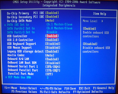
First, let's check if the USB controller is enabled. We go to "Integrated Peripherals". We go down with the arrow on the keyboard to the item “USB Controller”. Press the “Enter” key and in the window that appears, select “Enable” (also using “Enter”). Opposite “USB Controller 2.0” should also be “Enable”.
 Exit this tab by pressing Esc.
Then we go to "Advanced BIOS Features" - "Hard Disk Boot Priority".Now in my example, the hard drive is in the first place, and the flash drive should be.
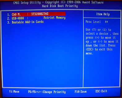 We stand on the line with the name of our flash drive (Patriot Memory) and raise it to the very top using the “+” key on the keyboard.
 Exit here by pressing "Esc".
Configuring AMI Bios to boot from a USB flash drive
If, upon entering BIOS, you see such a screen, then you have AMI Bios:
 First, let's check if the USB controller is enabled. Go to the tab "Advanced" - "USB Configuration".
 Opposite the items “USB Function” and “USB 2.0 Controller” should be “Enabled”.
 If this is not the case, we stand on this line and press the “Enter” key. From the list that appears, select “Enabled” (also using “Enter”).
Then exit this tab by pressing “Esc”.
Go to tab "Boot" - "Hard Disk Drives".
 Now I have a hard drive in the first place, but I need to put a USB flash drive here. We become on the first line, press “Enter” and in the window that appears, select our Patriot Memory flash drive.
 It should be like this:
 We leave from here through "Esc".
Select "Boot Device Priority". Here, the first boot device must be a USB flash drive.
 Press Esc.
Then we exit the BIOS, saving all the settings made. To do this, go to "Exit" - "Exit & Save Changes" - "OK".

Setting up Phoenix-Award Bios to boot from a USB flash drive
If, upon entering BIOS, you see such a screen, then you have Phoenix Award BIOS :
 First, let's check if the USB controller is enabled. We go to the “Peripherals” tab - opposite the items “USB Controller” and “USB 2.0 Controller” should be “Enabled”.
 Then we go to the “Advanced” tab and opposite “First Boot Device” we set “USB-HDD”.
 After that, exit the BIOS, saving the changes. To do this, go to "Exit" - "Save & Exit Setup" - press the key "Y" - "Enter"
 That's practically everything you need to know in order to boot from a USB flash drive. In my article, I described the process of setting up the Bios of the most popular versions: Award and AMI. The third example shows Phoenix Award Bios, which is much rarer.
In different versions of the BIOS, the described procedure may be slightly different. But the main thing is that you understand the principle of tuning itself.
By the way, I would also like to add: in order to choose which device to boot your computer from, it is not necessary to change the settings in the BIOS. You can call up a special menu immediately after turning on the computer to select boot devices (this can be done by pressing F8, F10, F11, F12 or Esc). In order not to guess with the keys, we look carefully at the monitor immediately after turning it on. We need to have time to see an inscription like this: “Press Esc to selest boot device”. In my case, it was necessary to press “Esc”.
This material describes almost all the parameters set in the Setup BIOS program from AWARD Software International Inc. In a particular motherboard, some of the described parameters may not be. The same parameters may be named differently depending on the manufacturer of the motherboard, so here in some cases there are several options.
BIOS FEATURES Setup
Virus Warning
Enabling this setting prevents any write to the boot sector of the hard drive without the user's permission. It was introduced to protect against so-called boot viruses that infect the boot sector. It is recommended to always enable this setting, but keep in mind that, for example, Windows 95 hangs during installation if Virus Warning is set to Enable (a black square appears on the screen).
Can take values:
- Enabled - allowed
- Disabled - prohibited
Boot Virus Detection (Detection of a virus in the boot sector)
The meaning of this parameter is very different from Virus Warning. The idea is as follows - if this option is disabled, then before the operating system is loaded, the BIOS rewrites the boot sector to flash memory and stores it there. After setting the parameter to Enabled, the BIOS will not boot the system from the hard drive if the content of the boot sector differs from that stored in memory. Further, at the discretion of the user, it is possible to either boot the system from a hard disk or from a floppy disk.
Can take values:
- Enabled - allowed
- Disabled - prohibited
CPU Internal Cache/External Cache
Enable/disable internal or external processor cache. Any type of cache memory should be disabled only if it is necessary to artificially slow down the computer, for example, when installing some old expansion card.
Can take values:
- Enabled - allowed
- Disabled - prohibited
CPU Level 1 Cache/CPU Level_2 Cache
Enable/Disable L1 cache and L2 processor cache for Pentium Pro architecture processors (Pentium II, Deshutes, etc.). Cache memory should be disabled only if it is necessary to artificially slow down the computer, for example, when installing some old expansion card.
Can take values:
- Enabled - allowed
- Disabled - prohibited
CPU Level 2 Cache ECC Check (Enable ECC for processor level 2 cache)
This parameter can be present only for boards with Pentium II architecture processors. It only makes sense to enable it if the installed Pentium II class processor has a L2 cache with ECC control capability.
Can take values:
- Enabled - allowed
- Disabled - prohibited
BIOS Update
Enabling this option allows you to update the BIOS microcode. In this case, new menu items may appear, with the help of which it is possible to fine-tune the system for individual cases (for example, cases of incompatibility).
Can take values:
- Enabled - allowed
- Disabled - prohibited
CPU Fast String
Enabling this parameter allows using some specific features of the Pentium Pro family architecture (Pentium II, Deshutes, etc.), in particular, the ability to cache operations with strings. It is only necessary to understand that the conditions for enabling this mechanism must be met in the program itself. These conditions are specified in the documentation for any processor of this family. It is recommended to leave the parameter in the "Enabled" state.
Can take values:
- Enabled - allowed
- Disabled - prohibited
Deturbo Mode
When this parameter is enabled, the FLUSH# signal becomes active and no data is then cached by the processor into its internal cache (first-level cache) by Pentium Pro architecture processors (Pentium II, Deshutes, etc.). Enabling this setting should only be used when you need to deliberately slow down your computer.
Can take values:
- Enabled - allowed
- Disabled - prohibited
Quick Power On Self Test
Enabling this parameter leads to a significant reduction in the time for the initial testing of the BIOS computer, especially with significant amounts of RAM. It should only be taken into account that the memory, for example, is not tested in this case, but only its size is checked.
Can take values:
- Enabled - allowed
- Disabled - prohibited
Boot Sequence
The parameter sets the sequence of polling devices from which the operating system can be loaded. These devices are identified either by letters for physical hard drives and conventional drives, or by the name of the device - CD-ROM for CD-ROM drives, LS for 120 Mb a:drive drives, or ZIP for 100 Mb ZIP IDE drives.
For modern versions, possible values might look like this:
- C only
- CD-ROM, C
- LS/ZIP, C
- etc.
Swap Floppy Drive
If enabled, drives A and B are sort of swapped. It makes sense only if there are 2 drives in the computer.
Can take values:
- Enabled - allowed
- Disabled - prohibited
Boot Up Floppy Seek (Search for a bootable drive after turning on the computer)
If this option is enabled, then the BIOS asks each drive to recognize its format (it supports 40_or 80 tracks). Since 40-track drives have not been released since 1993, this option should not be enabled, as the BIOS will spend several seconds each time figuring out the format of the drive.
Can take values:
- Enabled - allowed
- Disabled - prohibited
Boot Up NumLock Status
Enabling this setting turns on the NumLock indicator and the numeric keypad generates digit and character codes, otherwise it generates arrow codes, Ins, Del, etc.
Can take values:
- Enabled - allowed
- Disabled - prohibited
Typematic Rate Setting
Enables or disables setting the rate at which the keyboard repeats characters when a key is pressed.
Can take values:
- Enabled - allowed
- Disabled - prohibited
Typematic Rate (Chars/Sec)
The parameter has an effect only if the Typematic Rate Setting is enabled.
The repetition frequency has a number of fixed values, which this parameter can take:
Typematic Delay (Msec)
Sets the delay value from the moment a key is pressed until the keyboard starts repeating a character. Only has effect if the Typematic Rate Setting is enabled.
The value can be selected from the range:
PS/2 Mouse Function Control
Enabling this parameter only gives IRQ12 for the PS/2 mouse port. Otherwise, if there is no PS/2 mouse connected to the computer, IRQ12 is free for other devices. It is recommended to set the value to Auto.
Can take values:
- Enabled - enabled and IRQ12 is busy
- Auto - BIOS detects the presence or absence of a PS/2 mouse
OS/2 Onboard Memory > 64MB
Requires permission when two conditions are met - the computer has more than 64 Mb of memory installed and OS / 2 is used as the operating system.
Can take values:
- Enabled - allowed
- Disabled - prohibited
PCI/VGA Palette Snoop
The parameter should be enabled only if the colors are not displayed correctly on the screen. As a rule, this effect can occur when using such non-standard devices as MPEG cards, 3D accelerators and other similar devices.
Can take values:
- Enabled - allowed
- Disabled - prohibited
Video ROM BIOS Shadow (Video BIOS to Memory)
Enabling this option causes the video BIOS to be transferred from the ROM (Read Only Memory) on the video card to the main memory of the computer, which greatly speeds up the work with the video BIOS (this is necessary and visible in DOS). The acceleration is explained both by the fact that ROM access is much slower than RAM access, and by the fact that ROM access is in an 8-bit grid, and RAM access is in a 32-bit or 64-bit grid.
Can take values:
- Enabled - allowed
- Disabled - prohibited
Floppy Disk Access Control (R/W)
Enabling this option allows information to be written to the floppy, otherwise the floppy can be read. The parameter should be used to protect against unauthorized copying from a computer.
Can take values:
- Enabled - allowed
- Disabled - prohibited
CHIPSET FEATURES Setup
AUTO Configuration
Has 3 meanings:
- 60 ns - sets access parameters for DRAM with a speed of 60 ns
- 70 ns - same for 70 ns memory
- Disabled (disabled) - allows you to set any possible parameters for accessing DRAM memory
DRAM RAS# Precharge Time
This function allows you to determine the number of system bus cycles to generate the RAS signal. Decreasing this value improves performance, but reducing it too much for a particular memory can result in data loss.
Takes values:
DRAM R/W Leadoff Timing
Specifies the number of clocks on the bus before any DRAM operations are performed.
- 8/7 - eight bars for reading and seven bars for writing
- 7/5 - seven bars for reading and five bars for writing
DRAM RAS to CAS Delay
During memory accesses, column and row accesses are performed separately from each other. This parameter determines the state of one signal from another. Decreasing the value increases performance.
The parameter can take values:
- 3 - three cycle delay
- 2 - two cycles of delay.
DRAM Read Burst Timing
The read and write request is generated by the processor in four separate phases. In the first phase, an access to a specific memory area is initiated, and in the remaining phases, the data is actually read. Reducing the total number of cycles increases performance.
The parameter can take values:
- x2222 - two cycle delay
- x3333 - three cycle delay
- x4444 - four cycles of delay.
Speculative Leadoff
Enabling this parameter allows the read signal to be issued a little before the address is decoded. This technique reduces the overall time spent on a read operation. In other words, the processor will initiate the read signal at the same time as generating the address where the required data resides. The read signal is accepted by the DRAM controller, and if Speculative Leadoff is enabled, the controller will issue a read signal before address decoding is complete.
Can take values:
- Enabled - allowed
- Disabled - prohibited
Turn-Around Insertion (Delay between cycles)
If this parameter is enabled (Enabled), then one additional cycle is included between two consecutive memory access cycles. Resolution reduces performance, but increases the accuracy of read/write operations.
Can take values:
- Enabled - allowed
- Disabled - prohibited
Data Integrity (PAR/ECC)
Enables/disables memory check for errors. The type of control is set by the DRAM ECC/PARITY Select parameter. Memory modules that support this feature are required to enable this option.
Can take values:
- Enabled - allowed
- Disabled - prohibited
DRAM ECC/PARITY Select (Error Correction Mode/Parity Check)
The parameter appears only for the 430HX kit (for example, in the ASUSTeK P/I-P55T2P4 motherboard) or 440FX/LX, and only if true parity memory modules are installed. In some BIOS versions, only the type of verification can be set with this parameter, and the permission for verification is set by the Data Integrity (PAR / ECC) parameter. Such strips are often also called 36-bit.
Can take values:
- Parity - if an error occurs, a memory parity error message is displayed on the monitor and the computer stops working
- ECC - (Error Control Correction) in the event of a single error, it is corrected and work continues. If there is not a single error, then the computer also stops. It should only be taken into account that, according to Intel, the speed of exchange with memory when this mode is enabled decreases by approximately 3%.
Fast RAS# to CAS# Delay (Interval between RAS and CAS)
When refreshing memory, rows and columns are addressed separately, so this parameter sets the interval between the RAS and CAS signals.
SDRAM Configuration
The parameter determines whether BIOS program itself determine the timing of memory access based on information from the SPD block or allow the user to do this.
Can take values:
- By SPD - access parameters are set by SPD
- 7 ns (143 Mhz) - access parameters are set by the BIOS as for memory with an access time of 7 ns and a bus frequency of 143 MHz
- 8 ns (125 Mhz) - access parameters are set by the BIOS as for memory with an access time of 8 ns and a bus frequency of 125 MHz
- Disabled - set by the user
SDRAM RAS Precharge Time
The parameter allows you to define fast or slow accumulation of charge by RAS before the start of the memory regeneration cycle. Setting the Fast value increases performance, but Slow increases the stability of the computer, so you should set the Fast value if you are confident in the quality of the memory.
Can take values:
- Fast - fast
- Slow - slowly
SDRAM (CAS Lat/RAS-to-CAS) (Synchronous Memory - CAS Latency/RAS to CAS)
This parameter allows you to choose between the duration of the CAS signal and the delay between the RAS and CAS signals. The value of this parameter depends on the characteristics of the SDRAM used in the motherboard and on the speed of the processor. Therefore, changing this parameter should be done with extreme caution.
Can take values:
SDRAM CAS to RAS Delay (Delay between CAS and RAS)
This parameter defines the delay after the RAS signal is issued until the CAS signal for synchronous memory occurs. The smaller this value, the faster the memory access. However, you should change it carefully.
The parameter can take values:
- 3 - three cycle delay
- 2 - two cycles of delay
SDRAM CAS# Latency
Sets the CAS delay value for SDRAM. A smaller value increases system performance. It is recommended to set a lower value for SDRAM with a speed of 10 ns or better.
Can take values:
SDRAM Banks Close Policy
The parameter was introduced for boards with the 440LX kit due to the fact that memory with 2 banks organization does not work correctly in these boards if the parameters for accessing memory banks are set by default. In the 430TX set, this was not required, since the access rules for different memory were the same. You should only change the default BIOS settings for this setting if memory becomes unstable.
Can take values:
- Page Miss - used for dual bank memory
- Arbitration - for memory from 4 banks.
DRAM Idle Timer
This parameter sets the time (in ticks) until all open memory pages are closed. Affects both EDO and SDRAM memory.
Can take values:
Snoop Ahead (Prediction)
Enabling this setting allows data streaming between PCI and memory, predicting what data will be needed at the next point in time and thereby speeding up data transfer.
Can take values:
- Enabled - allowed
- Disabled - prohibited
Host Bus Fast Data Ready
Enabling this parameter will allow data to be taken from the bus at the same time as it is being sampled. Otherwise, the data will be held on the bus for one extra cycle.
Can take values:
- Enabled - allowed
- Disabled - prohibited
Refresh RAS# Assertion (RAS job for refresh)
This parameter sets the number of cycles (ie RAS duration) for the regeneration cycle. Accepted values are determined by the quality of the memory and the chipset (chipset). A smaller value improves performance.
MA Wait State
The parameter allows you to set or remove an additional waiting cycle before the start of reading the memory. For EDO memory, there is always one clock by default, and setting Slow adds one more wait clock. There is no default sleep clock for SDRAM and setting Slow to one clock introduces.
Can take values:
- Slow - one measure is added;
- Fast - no additional waiting cycle.
SDRAM Speculative Read (SDRAM advance reading)
Enabling this parameter allows the read signal to be issued a little before the address is decoded. This technique reduces the overall time spent on a read operation. In other words, the processor will initiate the read signal at the same time as generating the address where the required data resides. The read signal is accepted by the DRAM controller and, if the SDRAM Speculative Read parameter is enabled, the controller will issue a read signal before address decoding is complete.
Can take values:
- Enabled - allowed
- Disabled - prohibited
System BIOS Cacheable
Enabling this setting causes the memory area at system BIOS addresses F0000H to FFFFFH to be cached. The parameter will be used only if the use of cache memory is enabled in the BIOS Features Setup section. If any program tries to write to these addresses, the system will issue an error message.
Can take values:
- Enabled - allowed
- Disabled - prohibited
Video BIOS Cacheable
Enabling this setting causes the memory area at video card BIOS addresses C0000H to C7FFFH to be cached. The parameter will be used only if the use of cache memory is enabled in the BIOS Features Setup section. If any program tries to write to these addresses, the system will issue an error message.
Can take values:
- Enabled - allowed
- Disabled - prohibited
Video Memory Cache Mode
The parameter is valid only for Pentium Pro architecture processors (Pentium II, Deshutes, etc.). The Pentium Pro processor provided the ability to change the cache mode depending on a specific memory area through special internal registers called Memory Type Range Registers - MTRR. With the help of these registers, the modes UC (uncached - not cached), WC (write combining), WP (write protect), WT (write through - write-through) and WB ( write back - writeback). Setting the USWC mode (uncached, speculative write combining - do not cache, combined write mode) allows you to significantly speed up data output via the PCI bus to the video card (up to 90 MB/s instead of 8 MB/s). Note that the video card must support access to its memory in the range from A0000 - BFFFF (128 kB) and have a linear frame buffer. Therefore, it is better to set the mode to USWC, but in case of any problems (the system may not boot), set the default value to UC.
Can take values:
- UC (uncached) - not cached
- USWC (uncached, speculative write combining) - do not cache, combined write mode
Graphics Aperture Size (Graphic Aperture Size for AGP)
This parameter specifies the maximum size of the memory area to be used by a graphics card with an AGP interface. The default value, set on power-up or reset, is 4 MB. After BIOS initialization, it takes on the value selected by the motherboard manufacturer (usually 64 MB).
Allowed range of graphic aperture values:
- 16MB
- 32MB
- 64MB
- 128MB
- 256MB
PCI 2.1 Support (Support for the PCI 2.1 bus specification)
When this setting is enabled, PCI bus specification 2.1 features are supported. Specification 2.1 has two main differences from 2.0 - the maximum clock frequency of the bus is increased to 66 MHz and the PCI-PCI bridge mechanism is introduced, which allows removing the limitation of specification 2.0, according to which no more than 4 devices can be installed on the bus. It makes sense to disable this option only if problems occur after installing a PCI card (as a rule, they occur only with fairly old cards).
Can take values:
- Enabled - allowed
- Disabled - prohibited
8 Bit I/O Recovery Time
The parameter is measured in processor cycles and determines what delay the system will set after issuing a read / write request to the device (or, as is customary with Intel, the port) I / O. This delay is necessary because the read/write cycle for I/O devices is much longer than for memory. In addition, 8-bit I/O devices themselves tend to be slower than 16-bit I/O devices. The default value of this parameter is 1 and it should be increased only if some slow 8-bit device is installed in the computer.
Can take values: from 1 to 8 cycles.
16 Bit I/O Recovery Time
The parameter is measured in processor cycles and determines what delay the system will set after issuing a read / write request to the device (or, as is customary with Intel, the port) I / O. This delay is necessary because the read/write cycle for I/O devices is much longer than for memory. The default value for this setting is 1 and should only be increased if a slow 16-bit device is installed on the computer.
Can take values: from 1 to 4 cycles.
Memory Hole At 15M-16M ("Hole" in memory inside the 15th megabyte of memory)
Enabling this option allows you to access I / O devices as memory and thereby increase the speed of access to such devices. For the functioning of this mechanism, it is necessary to exclude for all ordinary programs the possibility of using a certain memory area (15 megabytes), which is what the BIOS does when this parameter is enabled. This option should be enabled if it is required in the documentation for the card installed in this computer.
Can take values:
- Enabled - allowed
- Disabled - prohibited
Peer Concurrency (Parallel work)
This setting enables or disables simultaneous operation of multiple devices on the PCI bus.
Can take values:
- Enabled - allowed
- Disabled - prohibited
Chipset Special Features
This parameter enables/disables all new features introduced in HX, VX or TX sets compared to FX.
Can take values:
- Enabled - allowed
- Disabled - prohibited
Passive Release
This parameter enables/disables the mechanism for parallel operation of ISA and PCI buses. If this option is enabled, then processor access to the PCI bus is allowed during passive partitioning. The need to disable this parameter may arise when using ISA boards that actively use DMA channels.
Can take values:
- Enabled - allowed
- Disabled - prohibited
PCI Delayed Transaction (Delayed transaction on PCI)
The presence of this parameter means that the motherboard has a built-in 32-bit buffer to support extended cycle time on PCI. If enabled, access to the PCI bus is allowed while accessing 8-bit devices on the ISA bus. This significantly increases performance, since the cycle of such access on the ISA takes 50-60 cycles of the PCI bus. If a card that does not support the PCI 2.1 specification is installed in the computer, this setting should be disabled.
Can take values:
- Enabled - allowed
- Disabled - prohibited
Parallel Port Mode (ECP+EPP)
This parameter allows you to set the operating modes of the parallel port. Please note that the exchange rate for some devices can be significantly increased by properly setting the printer port mode, for example, for external storage devices such as the Iomega ZIP Drive LPT.
Can take values:
- Normal - normal printer interface, also called SPP
- ECP - Enhanced Port
- EPP - extended printer port
- ECP+EPP - both modes can be used
ECP DMA Select (DMA channel selection for ECP mode)
The parameter appears only when ECP or ECP+EPP mode is enabled in Parallel Port Mode (ECP+EPP). Normal support for ECP mode requires a DMA channel, which is selected from channels 1 or 3.
Can take values:
- 1 - channel 1
- 3 - channel 3
- Disabled - it is forbidden to use DMA
There is also an item for selecting the EPP operating mode.
Can take values:
- EPP 1.9
- EPP 1.7
Onboard PCI IDE Enable
This parameter controls the enable/disable operation of each of the two channels of the IDE controller installed on the motherboard.
Can take values:
- Primary - only the first channel is allowed to work
- Secondary - only the second channel is allowed to work
- Both - both channels are allowed to work
- Disable - both channels are disabled
IDE PIO Mode (Selecting the operating mode of each drive)
Four options allow you to set each drive's operating modes individually, or allow the BIOS to automatically set the fastest mode for the drive. The allowed parameters are the same for each disk. For example, for IDE 0 Master Mode valid values are 0, 1, 2, 3, 4 and AUTO.
The UDMA setting can be set to Auto or Disable.
PnP/PCI Configuration Setup
PNP OS Installed (Is the operating system installed with Plug&Play support?)
Set to Yes if the operating system supports Plug&Play (for example, Windows 95) and No otherwise. If you select No, the BIOS must configure the Plug&Play devices.
Resources Controlled By (How resources are managed)
If AUTO is selected, the BIOS will automatically assign interrupts and DMA channels to all devices connected to the PCI bus and these options will not appear on the screen. Otherwise, all of these options must be set manually. In some BIOS versions, this parameter can be set individually for each PCI slot and look like this:
- Slot 1 IRQ
- Slot 2 IRQ
- etc.
Reset Configuration Data
It is recommended to set it to Disabled. When set to Enabled, the BIOS will clear the Extended System Configuration Data (ESCD) area, which stores data on the BIOS configuration of the system, so hardware conflicts are possible for devices "abandoned" in this way to the mercy of fate.
IRQ n Assigned to
Each system interrupt can be assigned one of the following device types: Legacy ISA (classic ISA cards) - Regular ISA cards such as modems or sound cards without Plug&Play support. These cards require interrupts to be assigned according to their documentation. PCI/ISA PnP (PCI bus devices or ISA devices with Plug&Play support) - this parameter is set only for devices on the PCI bus or ISA cards with Plug&Play support.
DMA n Assigned to
Each DMA channel on the system can be assigned one of the following device types: Legacy ISA (classic ISA cards) - Regular ISA cards such as modems or non-Plug&Play sound cards. These cards require DMA channel assignment according to their documentation. PCI/ISA PnP (PCI bus devices or ISA devices with Plug&Play support) - this parameter is set only for devices on the PCI bus or ISA cards with Plug&Play support.
PCI IRQ Activated by (Interrupts are activated by...)
The parameter can take the following values: Level (level) - the interrupt controller responds only to the signal level Edge (drop) - the interrupt controller responds only to the signal level drop.
PCI IDE IRQ Map to
Allows you to release the interrupts occupied by the IDE controller on the PCI bus if it is absent (or disabled) on the motherboard and give them to devices on the ISA bus. Standard interrupts for ISA are IRQ 14 for the first channel and IRQ 15 for the second channel.
Can take values:
- PCI IDE IRQ mapping (used for PCI IDE)
- PC AT (ISA) (used for ISA)
IRQ n Used By ISA (Interrupt n is used on the ISA bus)
The parameter is the same as IRQ n Assigned to and can take the following values:
- No/ICU (no/configuration utility for ISA) - if this value is set, then the BIOS can dispose of this interrupt as it sees fit. For DOS, configuration in this case can also be done using the ISA Configuration Utility from Intel
- Yes (yes) - means forced interrupt release for any card on the ISA bus that does not support Plug&Play mode. It is recommended that you always specify Yes for such cards and the interrupts they need, otherwise the BIOS can assign an interrupt that is hard used by some card on the ISA to another card, which can even cause the computer to stop working normally.
DMA n Used By ISA (DMA n channel is used on the ISA bus)
The parameter is the same as DMA n Assigned to and can take the following values:
- No/ICU (no/configuration utility for ISA) - if this value is set, then the BIOS can dispose of this DMA channel as it sees fit. For DOS, configuration options in this case can also be performed using the ISA Configuration Utility from Intel
- Yes (yes) - means forced release of the DMA channel for any card on the ISA bus that does not support Plug & Play mode. It is recommended that you always specify Yes for such cards and the DMA channels they need, otherwise the BIOS can assign a channel that is hard used by some card on the ISA to another card, which may even cause the computer to stop working normally.
ISA MEM Block BASE (Base address of the memory block for ISA)
Some cards for the ISA bus require access to memory located on such a card at certain addresses. Therefore, there was a need for this BIOS parameter.
Can take values:
- No/ICU (no/ICU) - leaves the control of this parameter to the discretion of the BIOS or ICU program
- C800, CC00, D000, D400, D800 and DC00 - indicates the address of the memory block.
In addition, an additional ISA MEM Block Size parameter appears, which is needed if there are several such ISA cards and this parameter can take values of 8K, 16K, 32K, 64K
Onboard AHA BIOS (BIOS of Adaptec Embedded SCSI Controller)
The parameter enables/disables execution of the BIOS of the embedded SCSI controller and thus enables/disables the operation of the embedded SCSI controller.
Can take values:
- AUTO (automatic) - Allowed to search for the Adaptec SCSI controller and start the BIOS for it
- Disabled - Set to this value when no SCSI card is present.
ONB AHA BIOS First
This parameter enables/disables BIOS startup of the onboard Adaptec controller prior to startup of any other SCSI controller.
Can take values:
- Yes - allowed
- No - prohibited
ONB SCSI SE Term. (Onboard SCSI controller terminators)
The parameter enables/disables connection of termination resistors (terminators) on the built-in SCSI controller.
Can take values:
- Enabled - allowed
- Disabled - prohibited
ONB SCSI LVD Term. (Onboard SCSI LVD controller terminators)
The parameter enables/disables connection of terminators (terminators) on the built-in SCSI LVD controller. Controlling this parameter allows you to increase the length of the connecting SCSI cable up to 25 meters.
Can take values:
- Enabled - allowed
- Disabled - prohibited
SYMBIOS SCSI BIOS or NCR SCSI BIOS
Permission to search for a SCSI controller based on the NCR 810 chip, used, for example, in the ASUS SC-200 card.
Can take values:
- AUTO (automatically) - Allowed to search for a SCSI controller and start the BIOS for it
- Disabled - Set to this value when there is no SCSI card
PCI Latency Timer
Sets the maximum time (in bus clock cycles) that a device on the PCI bus can hold the bus if another device requires access to the bus. The allowable range for changing this parameter is from 0 to 255 in increments of 8. The value of the parameter should be changed carefully, as it depends on the particular implementation of the motherboard.
USB IRQ (USB Bus Interrupt)
The parameter enables or disables the assignment of an interrupt for the USB bus controller. Because your computer often lacks interrupts, you should only enable this option if you have a USB device on your system.
Can take values:
- Enabled - allowed
- Disabled - prohibited
Power Management Setup
Power Management
Allows you to either allow the BIOS "to reduce the power consumption of the computer if it is not being worked on, or to prohibit it.
Can take values:
- User Define (defined by the user) - when setting this parameter, you can independently set the time for switching to low power mode
- Min Saving (minimum power saving) - when selected, the computer will go into low power mode after a period of 40 minutes to 2 hours (depends on the specific BIOS of the motherboard)
- Max Saving (maximum energy saving) - the computer will go into low power mode 10-30 seconds after the user stops working with it
- Disable (prohibition of power saving) - disables the power saving mode
Video Off Option (In which mode to turn off the monitor)
Allows you to set at what stage of "falling asleep" the computer to put the monitor into low power mode.
Can take values:
- Susp, Stby -> Off (shutdown in Suspend and Standby mode) - the monitor will go into low power mode when either Suspend or Standby mode occurs
- All modes -> Off (shutdown in all modes) - the monitor will be put into low power mode in any mode
- Always On (always on) - the monitor will never be put into low power mode
- Suspend -> Off (shutdown in Suspend mode) - the monitor will go into low power mode when Suspend mode occurs.
Video Off Method
Sets how the monitor enters the low power mode.
Can take values:
- DPMS OFF - reduce monitor power consumption to a minimum
- DPMS Reduce ON - the monitor is enabled and can be used
- DPMS Standby - monitor in low power mode
- DPMS Suspend - Super Low Power Monitor
- Blank Screen - the screen is blank, but the monitor consumes full power
- V/H SYNC + Blank - scan signals are removed - the monitor enters the lowest power consumption mode.
Suspend Switch
The parameter enables or disables the transition to the suspend mode (temporary stop) using the button on the system unit. To do this, you need to connect the SMI jumper on the motherboard to the button on the front panel. As a rule, either a special Sleep button or a Turbo button is used for this. The suspend mode is the mode maximum reduction computer power consumption.
Can take values:
- Enabled - allowed
- Disabled - prohibited
Doze Speed (CPU frequency in Doze mode)
Specifies the clock division ratio in Doze mode.
Stby Speed (CPU frequency in Standby mode)
Specifies the clock division ratio in Standby mode.
HDD Power Down
Sets either the time after which, if there is no access, the hard disk will be turned off, or prohibits such a shutdown at all. The setting has no effect on SCSI drives.
Can take values:
- 1 to 15 minutes
- Disabled - prohibited
Doze Mode
Sets the transition time or disables transition to the first stage of power reduction.
Can take values:
- 30 Sec, 1 Min, 2 Min, 4 Min, 8 Min, 20 Min, 30 Min, 40 Min, 1 Hour - transition time (Sec - seconds, Min - minutes, Hour - hour)
- Disabled - prohibited
Standby Mode
Sets the transition time or disables the transition to the second stage of power reduction.
Can take values:
- Disabled - prohibited
Suspend Mode
Sets the transition time or disables the transition to the third stage of power reduction.
Can take values:
- 30 Sec, 1 Min, 2 Min, 4 Min, 8 Min, 20 Min, 30 Min, 40 Min, 1 Hour - transition time (Sec - seconds, Min - minutes, Hour - hour)
- Disabled - prohibited
PM Events
In this section, those interrupts are indicated, from which the computer should "wake up" from the appeal, if there are calls to the devices using these interrupts.
IRQ 3 (Wake-up)
Enabling this setting will wake up the computer from a modem or mouse connected to COM2.
Can take values:
- Enabled - allowed
- Disabled - prohibited
IRQ 4 (Wake-up)
Enabling this setting will wake up the computer from a modem or mouse connected to COM1.
Can take values:
- Enabled - allowed
- Disabled - prohibited
IRQ 8 (Wake-up)
Enabling this option will wake up the computer from the real time clock. It is recommended to leave it disabled, as some programs may use the "alarm" function of the computer's clock for their own purposes.
Can take values:
- Enabled - allowed
- Disabled - prohibited
IRQ 12 (Wake-up)
Enabling this option will wake up the computer from a mouse connected to the PS/2 port.
Can take values:
- Enabled - allowed
- Disabled - prohibited
In the next section, those devices are indicated, with the activity of which the computer should not "fall asleep".
IRQ3 (COM2)
When this setting is enabled, the computer does not "sleep" if the device connected to the COM2 port is in use.
Can take values:
- Enabled - allowed
- Disabled - prohibited
IRQ4 (COM1)
When this setting is enabled, the computer does not "sleep" if the device connected to the COM1 port is in use.
Can take values:
- Enabled - allowed
- Disabled - prohibited
IRQ5 (LPT2)
When this setting is enabled, the computer does not "sleep" when a device connected to the LPT2 port (usually a printer) is in use.
Can take values:
- Enabled - allowed
- Disabled - prohibited
IRQ6 (Floppy Disk)
When this setting is enabled, the computer does not "sleep" when the floppy drive is accessed.
Can take values:
- Enabled - allowed
- Disabled - prohibited
IRQ7 (LPT1)
When this setting is enabled, the computer does not "sleep" when a device connected to the LPT1 port (usually a printer) is in use.
Can take values:
- Enabled - allowed
- Disabled - prohibited
IRQ 8 (RTC Alarm)
When this setting is enabled, the computer does not "sleep" when the RTC (Real Time Clock) is used as a timer. It is recommended to leave it disabled, as some programs may use the "alarm" function of the computer's clock for their own purposes.
Can take values:
- Enabled - allowed
- Disabled - prohibited
IRQ9 (IRQ2 Redir)
When this setting is enabled, the computer will not "sleep" if the device holding interrupt 9 (2) is in use.
Can take values:
- Enabled - allowed
- Disabled - prohibited
IRQ 10 (Reserved)
When this setting is enabled, the computer does not "sleep" if the device holding interrupt 10 is in use.
Can take values:
- Enabled - allowed
- Disabled - prohibited
IRQ 11 (Reserved)
When this setting is enabled, the computer does not "sleep" if the device occupying interrupt 11 is in use.
Can take values:
- Enabled - allowed
- Disabled - prohibited
IRQ 12 (PS/2 Mouse)
When this setting is enabled, the computer will not "sleep" if the device occupying interrupt 12 (a mouse connected to the PS/2 port) is in use.
Can take values:
- Enabled - allowed
- Disabled - prohibited
IRQ 13 (Coprocessor)
When this setting is enabled, the computer does not "sleep" if the coprocessor is in use.
Can take values:
- Enabled - allowed
- Disabled - prohibited
IRQ 14 (Hard Disk)
When this setting is enabled, the computer does not "sleep" if the hard drive on the first IDE channel is being accessed.
Can take values:
- Enabled - allowed
- Disabled - prohibited
IRQ 15 (Reserved)
When this setting is enabled, the computer does not "sleep" if the hard drive or CD-ROM is being accessed on the second IDE channel.
Can take values:
- Enabled - allowed
- Disabled - prohibited
power up control
The parameters in this section define the types of power supply control and apply to ATX standard power supplies and motherboards that can be connected to such a power supply.
PWR Button
Controls the functions of the Power button on the computer's system unit.
Can take values:
- Soft Off (software shutdown) - the button works like a normal computer power on / off button, but it is allowed to turn off the computer softly (for example, when exiting Windows95)
- Suspend (temporary stop) - when you press the power button for less than 4 seconds, the computer enters the Suspend stage of reducing power consumption
- No Function - The Power button becomes a regular power on/off button.
PWR Up On Modem Act
Enabling this setting allows you to turn on the computer when calling the modem.
Can take values:
- Enabled - allowed
- Disabled - prohibited
Wake On LAN
When this setting is enabled, the computer is turned on by a signal from the local network. Such inclusion is possible only if a network card that supports this mode is installed in the computer.
Can take values:
- Enabled - allowed
- Disabled - prohibited
AC PWR Loss Restart (Turn on the computer after a power failure)
Enabling this setting allows you to turn on the computer after a power failure. Otherwise, after power is restored, the computer will not turn on and you will need to press the Power button again.
Can take values:
- Enabled - allowed
- Disabled - prohibited
Automatic Power Up
Using this setting, you can turn on the computer daily at a specified time, or turn it on at a specified day and hour.
Can take values:
- Everyday (daily) - when you enter the time, the computer will turn on every day at the appointed time. The time is entered in the Time (hh: mm: ss) Alarm field in the order hours: minutes: seconds, either using the PgUp, PgDn keys, or by entering numbers directly.
- By Date (by date) - the computer will turn on on the specified day and at the specified time. When this option is selected, a field for entering the time appears (same as for Everyday) and a field for entering the day of the month. Date of Month Alarm - the day of the month - a number in the month is entered in this field. This automatically means that you can program the computer to turn on only within one month.
- Disabled - prohibited
In the following sections, the BIOS only reports the characteristics of some devices in the computer. Enabling parameters in these sections allows the BIOS to monitor these parameters and report them when they are out of range.
Fan Monitor Section
Chassis Fan Speed (xxxxRPM)
If Ignore is selected, this fan speed will not be monitored. This parameter will be displayed only when using a special fan with an additional output connected to a special connector on the motherboard. Otherwise, when you stop or critically reduce the speed of rotation, the BIOS will display a message on the screen before loading the operating system.
CPU Fan Speed (xxxxRPM) (CPU cooling fan speed control)
If Ignore is selected, this fan speed will not be monitored. This parameter will be displayed only when using a special fan with an additional output connected to a special connector on the motherboard. Otherwise, when you stop or critically reduce the speed of rotation, the BIOS will display a message on the screen before loading the operating system.
Power Fan Speed (xxxxRPM) (Power supply fan speed control)
If Ignore is selected, this fan speed will not be monitored. Otherwise, when you stop or critically reduce the speed of rotation, the BIOS will display a message on the screen before loading the operating system. Use of this parameter is possible with the appropriate power supply.
Thermal Monitor Section
CPU Temperature
Shows the CPU temperature in Celsius and Fahrenheit. If Ignore is selected, the temperature will not be monitored. Otherwise, if the temperature rises critically, the BIOS will display a message on the screen before loading the operating system.
MB Temperature
Shows the CPU temperature in Celsius and Fahrenheit. If Ignore is selected, the temperature will not be monitored. Otherwise, if the temperature rises critically, the BIOS will display a message on the screen before loading the operating system.
Voltage Monitor section
In this section, both the supply voltages supplied to the motherboard by the power source and those generated on the motherboard are displayed. These parameters do not require explanation, except for VCORE - this is the processor core supply voltage. This voltage is generated, as a rule, on the motherboard.