What does the parachute d 10 consist of. Specifications. Types of army "air umbrellas"
The main parachute is designed to provide a safe rate of descent and landing of the parachutist.
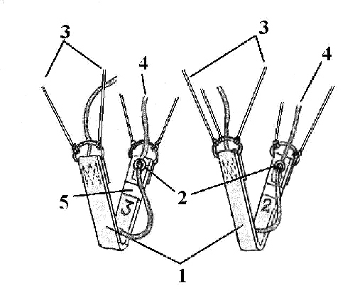
Main dome (view from below):
1 - dome wedges; 2 - a wedge made of "excelsior" fabric; 3 - gap; 4 - attachment points and numbers of external additional lines; 5 - attachment points and numbers of internal additional lines; 6-pole hole
Consists of the base of the dome and lines. The base of the dome consists of 24 wedges (1), which form a non-planar circle with an area of 100 m 2 . Each dome wedge, in turn, consists of seven wedges, six of which are made of nylon fabric, and one wedge (2) 50 mm wide is made of excelsior fabric, which is a mesh. The wedges are interconnected with a seam "in the lock". On the seams connecting the wedges of the dome, nylon ribbons LTKP-13-70 are stitched. The lower edge of the dome is reinforced on both sides with nylon tape LTKP-15-185. On the lower edge of the dome, all slings, except for slings No. 1A, 1B, 13A, 13B, have jumpers made of nylon tape LTKP-15-185, which are designed to prevent cases of overlapping of the dome with slings and reduce its filling time. On the basis of the canopy, between lines No. 1A and 1B, 13A and 13B there are slots (3) 1.7 m long, designed to turn the canopy during descent.

1 - main lines; 2 - external additional lines; 3 - internal additional lines; 4 - slings No. 1A, 1B, 13A, 13B; 5 - slings No. 2, 14; 6 - free ends of the suspension system.
The main parachute has 26 main lines (1) made of ShKP-150 nylon cord (including 22 lines 4 m long and 4 lines (4) attached to the loops of the canopy slots, 7 m long), 22 external additional lines (2) 3 m long, as well as 24 internal additional slings (3) made of ShKP-120 nylon cord, 4 m long.
Additional lines are attached to the main lines, and two additional internal lines (3) are attached to lines No. 2 and 14 (5).
The slings are tied at one end to the loops of the dome, at the other - to the half-ring buckles of the free ends (6) of the suspension system.
To facilitate the laying of the main parachute on lines No. 1A, 1B and on the additional line No. 24 at the lower edge of the canopy, as well as on the half-ring buckles of the suspension system, identification sleeves are sewn, made of green or blue cotton fabric, and on the additional line No. 12 - red or orange.
To facilitate the laying of lines, they are marked at a distance of 0.2 m from the lower edge of the dome and 0.4 m from the half-ring buckles of the free ends of the suspension system, indicating the beginning and end of laying.
On the lower edge of the dome, to the left of the lines, their serial numbers are indicated. On the outside of the canopy, between lines 1A and 24, there is a factory marking.
Lines No. 1A and 13A, 1B and 13B are sewn with control lines (4) (Fig. 26), which are designed to turn the dome and are made of a kapron cord ShKKr-190 of red color in two additions. The control lines are passed through the rings (2) sewn on the inside of the free ends (1) of the suspension system. One end of the left control line is attached to line No. 13A at a distance of 1.65 m, the other end is attached to line No. 1A at a distance of 1.45 m from the half-ring buckles of the free ends of the suspension system. One end of the right control sling is attached to the sling No. 13B at a distance of 1.65 m, the second - to the sling No. 1B at a distance of 1.45 m from the half-ring buckles of the free ends of the suspension system.
Control lines: 1 - free ends of the suspension system; 2 - rings; 3 - main lines; 4 - control lines; 5 - rubber belt loop
When tensioning the right control line, lines No. 1B and 13B are pulled, pulling the lower edge of the dome inward. The flow of air coming out from under the hem at the place of its hem creates a reactive force that rotates the dome, and it turns to the right. When pulling the left control line, lines No. 1A and 13A are pulled and the dome turns to the left.
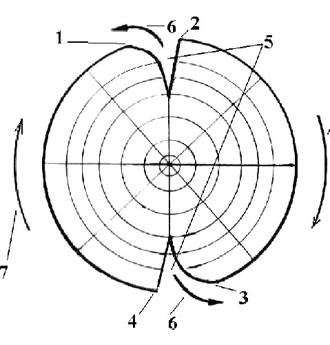
Turning the dome to the right (view of the dome from above): 1 - the place of attachment of the sling No. 1B; 2 - place of fastening of the sling No. 1A; 3 - place of fastening of the sling No. 13B; 4 - place of fastening of the sling No. 13A; 5 - slots of the dome; 6 - air outlet direction; 7 - dome rotation direction
Landing parachute D-10- This is the system that replaced the D-6 parachute. The area of the dome is 100 square meters with improved performance and beautiful appearance - in the shape of a squash.
Designed
Designed for jumps for both novice paratroopers and paratroopers - training and combat jumps from the AN-2 aircraft, MI-8 and MI-6 helicopters and AN-12, AN-26, AN-22, IL-76 military transport aircraft with full service armament and equipment ... or without it ... Throw speed 140-400 km / h, minimum jump height 200 meters with stabilization 3 seconds, maximum - 4000 meters with a parachutist flight weight up to 140 kg. Descent speed 5 m/sec.
Horizontal speed up to 3 m/sec. The forward movement of the canopy is carried out by rolling the free ends, where the free ends are reduced by rolling, the canopy goes there... Dome turns are carried out by control lines, the canopy is unfolded due to the slots located on the dome. The length of the lines for the D-10 parachute is different ... Lighter in weight, it got more control options ...
At the end of the article I will post the full performance characteristics of the D-10 (performance characteristics)
Parachute system D-10
Parachute system D-10 many people already know that the system came to the troops ... landing showed work in the air ... convergence became much less, because there are more opportunities under an open dome to run to where there is no one ... with a parachute it will be even better in this regard .. Believe me, it's difficult ... to create a system that opens safely, give speed to the canopy, make turns, create such control that a paratrooper without jumping experience can handle it ... but for paratroopers when they go with full service weapons and equipment, maintain the rate of descent and allow easy control of the canopy ...
And in a combat situation during the landing, it is necessary to exclude as much as possible shooting-shooting at paratroopers, as at targets ...
The Research Institute of Parachute Engineering has developed a modification of the D-10 parachute... get to know...
From a height of 70 meters

The minimum drop height is 70 meters...! We have courageous paratroopers... it's scary to walk from 100 meters... :)) it's scary, because the ground is close... and from 70 meters... it's like heading into a whirlpool... :)) the ground is very close. .. I know this height, this is the approach to the last straight line on the sports dome ... but the D-10P system has been worked out for quick opening ... without stabilization for the forced opening of the knapsack ... the pull rope is attached with a carabiner to the cable in an airplane or helicopter, and the other end with a cable to close the parachute bag ... the cable is pulled out with a rope, the bag opened and the canopy went ... such an opening system for the D-1-8 parachute, series 6 ... the possibility of leaving the aircraft at a height of 70 meters is safety while landing in combat conditions ...
The maximum altitude of leaving the aircraft is 4000 meters...
The D-10P system is designed in such a way that it can be converted into the D-10 system ... and vice versa ... in other words, it can be operated without stabilization for the forced opening of the parachute or stabilization is attached, the parachute fits into work with stabilization and forward, into Sky...
The dome consists of 24 wedges, slings with a breaking strength of 150 kg each...
22 slings 4 meters long and four slings attached to the loops of the dome slots, 7 m long, made of ShKP-150 nylon cord,
22 external additional slings from the ShKP-150 cord, 3 m long
24 internal additional slings from the ShKP-120 cord, 4 m long, attached to the main slings ... two internal additional slings are attached to lines 2 and 14.
The performance characteristics of the PDS D-10
| Weight of a paratrooper with parachutes, kg | 140-150 |
| Aircraft flight speed, km/h | 140-400 |
| Maximum safe parachute opening height, m | 4000 |
| Minimum safe application height, m | 200 |
| Stabilization time, s | 3 or more |
| Speed of descent on a stabilizing parachute, m/s | 30-40 |
| The force required to open a two-cone lock using a manual opening link, kgf | no more than 16 |
| Speed of descent on the main parachute, m/s | 5 |
| Time to turn in any direction by 180 when the lock cord is removed and the free ends of the harness are pulled, s | no more than 60 |
| Time to turn in any direction by 180 with locked free ends of the suspension system, s | no more than 30 |
| Average horizontal forward and backward speed, m/s | not less than 2.6 |
| Weight of parachute system without parachute bag and parachute device AD-3U-D-165, kg, | no more than 11.7 |
| Number of applications | |
| with a total flight weight of a paratrooper-paratrooper of 140 kg, | times 80 |
| including with a total flight weight of a parachutist 150 kg | 10 |
| Shelf life without repacking, months | no more than 3 |
| Warranty period, years | 14 |
The D-10 parachute system allows the use of reserve parachutes of the Z-4, Z-5, Z-2 types. Parachute devices AD-3U-D-165, PPK-U-165A-D are used as a safety device for opening a two-cone lock.
Purpose, device and interaction of parts
The landing parachute system D-10 is designed for training and combat jumps from the An-22, Il-76, An-26 military transport aircraft, from the An-2 aircraft and Mi-6 and Mi-8 helicopters, performed by separate paratroopers or groups of paratroopers of all specialties with full service weapons and equipment or without it, with a total flight weight of a paratrooper of 140 kg.
Technical and operational characteristics
| Operating restrictions: | |
| weight of a paratrooper with parachutes, kg | 140 – 150 |
| aircraft flight speed, km/h | 140 – 400 |
| maximum safe parachute opening height, m | |
| minimum safe application height, m | |
| Stabilization time, s | 3 or more |
| Speed of descent on a stabilizing parachute, m/s | 30 – 40 |
| The force required to open a two-cone lock using a manual opening link, kgf, no more | |
| Speed of descent on the main parachute, m/s | |
| Time to turn in any direction by 180 0 when the lock cord is removed and the free ends of the suspension system are pulled, s | no more than 60 |
| Time to turn in any direction by 180 0 with locked free ends of the suspension system, s | no more |
| Average horizontal forward and backward speed, m/s | not less than 2.6 |
| Height of a paratrooper-paratrooper, m | 1,5 – 1,9 |
| Weight of parachute system without parachute bag and parachute device AD-3U-D-165, kg, no more | 11,7 |
| Number of uses: | |
| with a total flight weight of a paratrooper-paratrooper of 140 kg, times | |
| including with a total flight weight of a parachutist 150 kg | |
| Shelf life without repacking, months, no more | |
| Warranty period, years | |
| It is allowed to increase the service life, years | up to 20 |
The D-10 parachute system allows the use of reserve parachutes of the Z-4, Z-5, Z-2 types. Parachute devices AD-3U-D-165, PPK-U-165A-D are used as a safety device for opening a two-cone lock. Parts of the parachute system are inseparable, which excludes their disconnection during the entire landing process.
Parts of the parachute system
1. Camera of the stabilizing system.
2. Stabilizing system (stabilizing strapless parachute).
3. Main parachute chamber.
4. Main parachute (dome with lines).
5. Suspension system.
7. Double cone lock.
8. Manual opening link.
9. Safety parachute device type PPK-U or AD-ZU-D.
10. Parachute bag.
11. Passport.
12. Auxiliary parts and details.
Camera Stabilization System(Fig. 1.20) is intended for laying the stabilizing dome with slings and the upper part of the stabilizer into it, as well as for the orderly commissioning of the stabilizing system.
The shape is cylindrical. Material - kapron advice. It consists of a base (4) and those on it: in the upper part - a carabiner (1) for attaching to a cable or extension in an airplane, a lashing tape (7) for tying in a rubber honeycomb, a fuse (6) , drawstring cord (3) for tightening the camera; at the bottom - metal rings (5) for locking with stabilizer rings.

Stabilizing system (stabilizing strapless parachute) It is designed to put into operation a safety parachute device, to ensure a stabilized descent of the parachutist and to open the main parachute.
Stabilizing system ( rice. 1.21 ) consists of a canopy with lines and a stabilizer with a parachute link.


| |
In the pole part of the dome there is an exhaust device (2), which is designed to ensure the filling of the dome and consists of eight pockets. Reinforcing tapes are sewn on the outer side of the dome: radial (3) - from the tape LTKP-15-185 and circular (4) from the tape LTKP-13-70. The edge of the dome is reinforced by folding the fabric to the outer side and stitched onto it on both sides with an LTKP-15-185 tape. Along the lower edge of the dome, under the radial reinforcing tapes, the ends of 16 slings made of the ShKP-200 cord are threaded and attached in a zigzag stitch. The length of the outer lines (6) in the free state from the lower edge of the canopy to the stabilizer feather is 0.52 m, and the middle lines (5) are 0.5 m. The canopy has a factory stamp (18): parachute index and year of manufacture.
The stabilizer serves to prevent rotation of the stabilizing parachute and consists of two feathers (7), each of which is made of gray nylon fabric and has the shape of an isosceles triangle. The feathers are stitched in height to form four stabilizer feathers. On the sides of each feather, LTKrP-26-600 ribbons are sewn, forming loops in the upper part, to which lines are attached, and in the lower part passing into a parachute link. A ribbon with a ring (17) is sewn on each side of the feather. The rings serve for locking them with the rings sewn on the chamber of the stabilizing parachute.
The parachute link (8) serves to connect the stabilizing parachute to the satchel during the stabilization stage and to the main canopy at all other stages of work, as well as to remove the stabilizing parachute from the paratrooper and ensure its stable operation. At a distance of 0.45 m from the stabilizer feathers, a loop (9) from the LTKrP-26-600 tape is sewn onto the link, which is intended for attaching the cord for turning on the parachute device. The lower part of the link branches out, forming power tapes (10), at the ends of which buckles (11) of a two-cone lock are sewn. Jumpers made of LTK-44-1600 tape are sewn on both sides of the power tapes. A loop (13) of LTKMkrP-27-1200 tape is sewn between the jumpers, which is designed to attach the stabilizing system to the bridle of the main parachute canopy and to the bridle of its chamber. On the loop there is a check-in tape (12) made of LTKrP-26-600 red nylon tape in three additions and designed for check-in of a removable honeycomb located on the ring of the right valve of the knapsack. One of the lashing concentrators has a loop for attaching to the loop of the parachute link of the stabilizing parachute, the other has a mark limiting the lashing.
The triangle formed from the ribbons is closed on both sides with kerchiefs (14) made of nylon advisor. A guide ring (16) is sewn onto the power tapes between the scarves using tape (15) LTKrP-26-600, through which the parachute device activation cord is passed. On the power tapes near the buckles, arrows are applied with black harmless paint to control the correct installation and installation of power tapes on a two-cone lock.
Parachute stabilizing strapless(Fig. 1.22) consists of a dome, a stabilizer and a parachute link.

 The dome (1) has a hemispherical shape with an area of 1.5 m 2 and is made of nylon fabric. Radial reinforcing tapes (3)LTKP-15-185 and circular tapes (2)LTKP-13-70 are stitched on the outer side of the dome. The edge of the dome is reinforced with LTKP-15-185 tape stitched onto it on both sides. The canopy is marked with a factory stamp: parachute index and year of manufacture. _____________________________
The stabilizer serves to prevent rotation of the stabilizing parachute and consists of four feathers (4), which are made of gray nylon fabric. On the surface of each stabilizer feather, on both sides, a reinforcing frame made of LTKP-13-70 tape is sewn. The upper side of each feather is attached to the dome with the help of the bifurcated ends of the reinforcing frame tapes. On the sides of each feather, LTKrP-26-600 ribbons are sewn, which form a parachute link in the lower part. A ribbon with a ring (15) is sewn on each side of the feather. The rings serve for locking them with the rings sewn on the chamber of the stabilizing parachute.
The parachute link (5) is used to connect the stabilizing parachute to the backpack during the stabilization stage and to the main canopy at all other stages of operation, as well as to remove the stabilizing parachute from the main parachute and ensure its stable operation. At a distance of 0.45 m from the stabilizer feathers, a loop (6) from the LTKrP-26-600 tape is sewn onto the link, which is intended for attaching the cord for turning on the parachute device. The lower part of the link branches out, forming power tapes (7), at the ends of which buckles (8) of a two-cone lock are sewn. Jumpers made of LTK-44-1600 tape are sewn on both sides of the power tapes. A loop (10) of LTKMkrP-27-1200 tape is sewn between the jumpers, which is intended for attaching a stabilizing parachute to the bridle of the main parachute canopy and to the bridle of its chamber. On the loop there is a lashing tape (9) made of LTKrP-26-600 nylon tape of red color in three additions and designed for buckling a removable honeycomb located on the ring of the right valve of the knapsack. On one end of the lashing there is a loop for attaching to the loop of the parachute link of the stabilizing parachute, on the other there is a mark limiting the lashing.
The triangle formed from the ribbons is closed on both sides with kerchiefs (11) made of nylon advisor. A guide ring (13) is sewn onto the power tapes between the scarves using tape (12) LTKrP-26-600, through which the parachute device activation cord is passed. On the power tapes near the buckles, arrows are applied with black harmless paint to control the correct installation and installation of power tapes on a two-cone lock.
Main parachute chamber(fig. 1.23) is used for laying the canopy with the lines of the main parachute into it and for its orderly opening. The camera is made of gray nylon fabric and has the shape of a cylinder (when folded).

 The surface of the chamber is reinforced with two tapes (2)LTKrP-26-600, which form a bridle in the upper part. For the convenience of laying the dome in the chamber along the upper base of the chamber and the bridle ribbons, our scarf (5). A cord-tie (3) from the ShKP-150 cord, which is designed to tighten the upper base of the chamber, is inserted and attached to the under-bend of the upper base of the camera.
On the base of the camera is sewn:
Nine straight (10) combs with ribbons (11) at the bottom for laying main parachute lines:
Honeycomb spreader (8) with honeycomb rubber (9) from knapsack cord to hold the lines in the comb;
Valve (15) with two pairs of eyelets (14) for passing removable rubber honeycombs (16, 17) and with two pockets (21) for covering bundles of lines; for the convenience of laying the slings, the valve near the eyelets is marked - 1,2,3,4;
Pocket (22) at the top base of the chamber for threading the ends of the cord-tie.
To cover the bundles of slings laid in honeycombs, aprons (7) made of gray nylon fabric with tie ribbons (6) are sewn in the upper part of the chamber.
A ring (20) of an elastic band 29 mm wide is inserted into the hem of the lower part of the chamber, designed to ensure an orderly exit of the main parachute canopy from the chamber.
At the lower base of the chamber, two removable rubber honeycombs are installed and an apron (19) is sewn on, which in turn has two more removable rubber honeycombs.
main parachute(Fig. 1.24) is designed to ensure a safe speed of descent and landing of a parachutist.
Consists of the base of the dome and lines. The base of the dome consists of 24 wedges (1), which form a non-planar circle with an area of 100 m 2 . Each wedge of the dome, in turn, consists of seven wedges, six of which are made of nylon fabric, and one wedge (2) 50 mm wide is made of excelsior fabric, which is a mesh. The wedges are interconnected with a seam "in the lock". On the seams connecting the wedges of the dome, nylon ribbons LTKP-13-70 are stitched. The lower edge of the dome is reinforced on both sides with nylon tape LTKP-15-185. On the lower edge of the dome, all slings, except for slings No. 1A, 1B, 13A, 13B, have jumpers made of nylon tape LTKP-15-185, which are designed to prevent cases of overlapping of the dome with slings and reduce its filling time. On the basis of the canopy, between lines No. 1A and 1B, 13A and 13B there are slots (3) 1.7 m long, designed to turn the canopy during descent. The main parachute (Fig. 1.25) has 26 main lines (1) made of ShKP-150 nylon cord (of which 22 lines are 4 m long and 4 lines (4) are attached to the loops of the canopy slots, 7 m long), 22 are external additional slings (2) 3 m long , as well as 24 internal additional slings (3) from a kapron cord ShKP-120 4 m long.

Additional lines are attached to the main lines, and two additional internal lines (3) are attached to lines No. 2 and 14 (5). The slings are tied at one end to the loops of the dome, at the other - to the half-ring buckles of the free ends (6) of the suspension system.
To facilitate the laying of the main parachute on lines No. 1A, 1B and on an additional line No. 24 at the lower edge of the canopy, as well as at the half-buckles

The front of the suspension system is sewn with identification sleeves made of green or blue cotton fabric, and on the additional line No. 12 - red or orange.
To facilitate the laying of lines, they are marked at a distance of 0.2 m from the lower edge of the dome and 0.4 m from the half-ring buckles of the free ends of the suspension system, indicating the beginning and end of laying.
On the lower edge of the dome, to the left of the lines, their serial numbers are indicated. On the outside of the canopy, between lines 1A and 24, there is a factory marking. On slings No. 1A and 13A, 1B and 13B, control lines (4) are sewn (Fig. 1.26) ,
which are designed to turn the dome and are made of kapron cord ShKKr-190 of red color in two additions. The control lines are threaded through rings (2) sewn on the inside of the free ends (1) of the harness. One end of the left control line is attached to the line 
 pe No. 13A at a distance of 1.65 m, the second - to the line No. 1A at a distance of 1.45 m from the half-ring buckles of the free ends of the suspension system. One end of the right control line is attached to the line No. 13B at a distance of 1.65 m, the second - to the line No. 1B at a distance of 1.45 m from the half-ring buckles of the free ends of the suspension system.
When tensioning the right control line, lines No. 1B and 13B are pulled, pulling the lower edge of the dome inward. The air flow coming out from under the edge at the place of its hem creates a reactive force that rotates the dome, and it turns to the right (Fig. 1.27).

 _________________________________
When the left control line is pulled, lines No. 1A and 13A are pulled and the canopy turns to the left.
suspension system parachute is intended:
For connecting a parachute to a parachutist;
For uniform distribution of the dynamic load on the parachutist's body at the moment of opening the parachute;
For convenient placement of a parachutist in it, for attaching a reserve parachute, weapons and equipment.
 The suspension system (Fig. 1.28) is made of LTK-44-1600 nylon tape and consists of the following parts:
Loose ends (1);
Main girth (2);
Back and shoulder girths (3);
Breast jumper (4);
Waist girth (5);
Leg loops (6);
Pinning device (7).
 __________________________________
Loose ends marked with numbers: 1 and 2 - the right pair, 3 and 4 - the left and end with half-ring buckles, to which the main parachute lines are attached. At the free ends, marked with the numbers 2 and 3, there are rubber loops made of elastic tape, designed to fill the slack in the control lines. In the upper part of the free ends, four ribbons with rings are sewn, through which the control lines are passed.
Each pair of free ends has a locking cord made of ShKP-150 cord, which is used when using a parachute system without rolling over the free ends of the harness.
Main Girth stitched from ribbons in two additions. On the left in the upper part of the main girth there are two curved buckles: the lower one for connecting it with the left back-shoulder girth, the upper one for fastening the left pair of free ends.
On the right in the upper part of the main girth there are three curved buckles: the lower one for connecting it with the right dorsal-shoulder girth, the upper _ for fastening the link of the pinning device made of the LTKP-43-900 tape and the right detachable pair of free ends, the middle one -
for mounting the link of the pinning device.
On the reverse side of the main girth, below the curved buckles, with the help of the tape LTKrP-43-800, buckles are sewn for fastening the belts of the cargo container.
On the left side of the main girth, below the curved buckles, a LTKkrP-26-600 tape is sewn for attaching a flexible hose, and below, at chest level, a pocket for a manual opening link is sewn.
To attach the free ends of the intermediate suspension system of the reserve parachute, two fastening brackets are mounted in the main girth.
Below, with the help of tape LTKrP-43-800, buckles are sewn into the main girth for pulling up the knapsack with the help of adjusting tapes. Here, in the triangles formed by the straps of the back-shoulder girths, a carabiner is fixed on the left side, and on the right side there is a buckle for fastening the leg girths. In the lower part, the main girth is bifurcated, the tapes are sewn end-to-end, and they are sewn with a soft pad for comfortable sitting in the suspension system and rings for pulling up the lower corners of the pack.


Back and shoulder girths to exclude spontaneous movement through curved buckles and buckles with toothed bridges, they have LTKkrP-43-800 tapes sewn on them and loops from LTKkrP-43-800 tape.
chest jumper formed by dorsal-shoulder girths going up from the crosspiece through curved buckles, and has a carabiner in the left half, and a buckle in the right.
Leg loops formed by the lower ends of the back-shoulder girths, passed between the ribbons of the main girth, and have a carabiner on the right girth, and a buckle on the left. Rectangular buckles are mounted on the leg loops for adjusting the leg loops according to the height of the parachutist.
Waist girth formed by ribbons of the chest bridge after passing them between the ribbons of the main girth; it has two rectangular adjustment buckles
Pinning device(Fig. 1.30) is designed to disconnect the right pair of free ends from the suspension system and is made of lightweight tape LTKOkr-44-1600, on which are sewn:
Tape LTKMP-12-450, forming a loop to which a pin-check is attached;
Tape LTKP-15-185, forming a loop for fastening the pinning device to the curved buckle of the main girth;
Tape LTKrP-26-600 forming a handle.
A textile fastener is sewn on the ends of the tape LTKOkr-44-1600. A removable parachute honeycomb is fixed on the pin-pin ring.
knapsack(Fig. 1.31) is intended for laying in it the canopy of the main parachute with lines, laid in the chamber, part of the free ends of the harness and placing the device.
The knapsack is made of nylon avisent or nylon fabric and consists of a base, false bottom, right and left flaps. A stiffening frame is inserted between the main and false bottom.
On the right flap there is a pocket of the device made of LTKrP-26-600 tape with tie ribbons and a pocket of the parachute device activation cord made of LTK-44-1600 tape with a valve. Attached to the top of the right flap is a rubber honeycomb for mounting a stacked stabilizing system on top of the pack. On the outside of the right valve there is a handle made of LTKrP-26-600 tape, which is designed to pull the right valve back when filling the slack link of the stabilizing parachute under it in preparation for making a parachute jump from the Il-76 aircraft.
Rings are sewn into the free corners of the right and left valves of the backpack, designed to hold the valves in a tightened state.
 A removable honeycomb is mounted on the ring of the right valve, and a welded ring is sewn on the upper part of the backpack, on the outer side of the left valve, on the backpack, designed to secure the removable honeycomb with a tape located on the loop of the parachute link of the stabilizing system.

At the beginning of the stitching of the right flap, a wire ring was sewn with the help of the tape LTKrP-20-150, designed to lock the fastening loop of the cord for turning on the parachute device. On the same section of the right valve there is a loop with a button spike for the valve covering the two-cone lock. In the upper part of the knapsack, under the fastening plate of the two-cone lock, with the help of the tape LTKrP-20-150, a ring is fixed, designed to pass through the rubber honeycomb, which fastens the laid stabilizing system on the upper part of the knapsack. On the opposite side, there is a second loop with a button spike for a valve that covers a two-cone lock. On the left side of the satchel, one end of a flexible hose is fixed on a buckle with a toothed bridge, which is designed to accommodate the cable of the manual opening link and protect it from accidental snagging (hose length - 0.38 m).
At the top of the stiffening frame there are two round and four oblong holes (Fig. 1.32). In the two upper elongated holes, LTKkrP-43-800 ribbons are fixed, which end with buckles with toothed bridges and are designed to fasten the satchel to the dorsal-shoulder girths of the suspension system. Regulating bands LTKMkrP-27-1200 are fixed in two lower longitudinal holes.
Note: a stiffening frame with two windows at the top is allowed
parts of a backpack. On this satchel there are ribbons ending in yarn
kami with serrated bridges, fixed in the upper
side, and adjusting tapes - at the bottom of the windows.
On the inside of the knapsack at a distance of 0.26 m from the top there is a mark that limits the laying of the free ends on the knapsack.
Based on the knapsack, the following are scribbled:
Eight loops for fastening the backpack to the suspension system;
Two-cone lock valve;
Two scarves.

 The kerchiefs are equipped with round buckles with floating bridges, in which LTKkrP-26-600 straps for fastening the reserve parachute are threaded, ending with carbines, and orange ribbons LTKkrP-26-600, which are designed to quickly release the straps for fastening the reserve parachute. On the left scarf there is a pocket for a card that replaces a passport. Above the sewing of the right scarf on the knapsack, two ties are sewn for attaching the device hose. On the lower corners of the knapsack, two pull-up tapes are sewn, made of LTKrP-26-600 tape in two additions and designed to attract the lower corners of the knapsack to the suspension system.
Double cone lock(Fig. 1.33) is designed to hold the buckles of the power tapes of the stabilizing system during stabilization and release them when the manual opening link is pulled out or the parachute device is triggered. The two-cone lock includes the following parts:
Mounting plate;
Housing with two cones;
Shutter with two cones;
Two shock absorbers;
Spring and adjusting washers;
mounting plate;
Cover screw;
5 fastening screws;


W manual opening vein(Fig. 1.34) is designed to open the two-cone lock by the parachutist himself. It consists of a ring made of steel  bar; rope 0.6 m long; limiter and wire loop. Cable link manual opening at a distance of 0.21 m from the limiter and 0.057 m from the loop
covered with polyethylene  oloch. Manual link allowed
openings without a polyethylene sheath on a cable.
 Safety parachute device(Fig. 1.35) is designed to open a two-cone lock in case the skydiver for some reason did not pull out the manual opening link.
____________________________

| |
With parachute system D-10
devices of the type PPK-U-165A-D and AD-3U-D-165 are used with hoses 0.165 m long, cables 0.322 m long, loops 0.019 m long and switching cords 0.36 m long with flexible pins.
 parachute bag(Fig. 1.36) is intended for laying the parachute system in it during transportation and storage.
_____________________
 Rectangular parachute bag, made of avisent and has: two handles, a loop for a tag, a flap with two half-ring buckles, a cord for tightening the bag, a tag for sealing the bag, a tape for tightening the valve and a pocket.
The passport is an integral part of the parachute system and is designed to keep records of the reception, transfer, securing, maintenance, operation, repair and modification of the parachute system.
To auxiliary parts include safety thread and safety cord SHHB-20.
Safety thread they will lock the loop of the link of the stabilizing system with the ring on the knapsack, the flexible pin in the shutter of the parachute device, the shutter of the two-cone lock.
It is made of cotton yarn (you can use the core of the cord ШХБ-125, ШХБ-60).
Safety cord 0.3 m long, the rings of the stabilizer feathers are hidden with the rings of the camera of the stabilizing system, while when landing from the An-2 aircraft, the Mi-8 helicopter, the ShHB-20 is used in two additions, from the Il-76 aircraft - in one addition.
Landing parachute D-10- This is the system that replaced the D-6 parachute. Dome area 100 sq. m with improved performance and beautiful appearance - in the form of a squash.
Designed
Designed for jumps for both novice paratroopers and paratroopers - training and combat jumps from the AN-2 aircraft, MI-8 and MI-6 helicopters and AN-12, AN-26, AN-22, IL-76 military transport aircraft with full service weapons and equipment. or without it. Throw speed 140-400 km/h, minimum jump height 200 meters with stabilization 3 seconds, maximum jump height 4000 meters with a parachutist flight weight up to 140 kg. Descent speed 5 m/sec.
Horizontal speed up to 3 m/sec. Moving the dome forward is carried out by rolling the free ends, where the free ends are reduced by rolling, and the dome went there. Dome turns are carried out by control lines, the dome is turned due to the slots located on the dome. The length of the lines for the D-10 parachute is different. Lighter in weight, he got more control options.
At the end of the article I will post the full performance characteristics of the D-10 (performance characteristics)
Parachute system D-10
Parachute system D-10 many people already know that the system has come to the troops. landing showed work in the air. there are significantly fewer convergences, because there are more opportunities under an open dome to run to where there is no one. with the D-12 parachute system it will be even better in this regard. Believe me, it's hard. create a system that opens safely, give speed to the canopy, make turns, create such a control that a skydiver without jumping experience can handle it. and for the paratroopers, when they go with full service weapons and equipment, to keep the rate of descent and allow easy control of the canopy.
And in a combat situation during the landing, it is necessary to exclude as much as possible shooting-shooting at paratroopers, as at targets.
The Research Institute of Parachute Engineering has developed a modification of the D-10 parachute. get acquainted.
From a height of 70 meters
The minimum drop height is 70 meters. We have courageous paratroopers. it's scary to walk from 100 meters.)) it's scary, because the ground is close. and from 70 m. it's like heading into a whirlpool.)) the earth is very close. I know this height, this is the approach to the last straight line on the sports dome. but the D-10P system has been worked out for a quick opening. without stabilization for forced opening of the knapsack. the pull rope is fastened with a carabiner to the cable in an airplane or helicopter, and the other end is fastened with a cable to close the parachute pack. the cable is pulled out with a rope, the knapsack opened and the dome went. such an opening system for the parachute D-1-8, series 6. the possibility of leaving the aircraft at a height of 70 meters is safety during landing in combat conditions.
The maximum altitude of leaving the aircraft is 4000 meters.
The D-10P system is designed so that it can be converted to the D-10 system. and vice versa. in other words, it can be worked without stabilization for forced opening of the parachute or stabilization is attached, the parachute is put to work with stabilization and forward into the sky.
The dome consists of 24 wedges, slings with a breaking strength of 150 kg each.
22 slings 4 meters long and four slings attached to the loops of the dome slots, 7 m long, made of ShKP-150 nylon cord,
22 external additional slings from the ShKP-150 cord, 3 m long
24 internal additional slings from the ShKP-120 cord, 4 m long, attached to the main slings. to slings 2 and 14, two additional internal slings are attached.
PARACHUTE D-10
PARACHUTE OF D-10
08.06.2013
NEW PARACHUTES HAVE BEEN IN SERVICE IN THE AIR AND STORM UNION OF THE SOUTH VO
Guardsmen of the air assault unit of the Southern Military District (SMD), stationed in the Volgograd region, have begun to master the new D-10 parachutes, which entered service with the unit this year.
The personnel were trained on the installation of a new parachute and the procedure for its laying, training at the airborne complex, after which the military personnel began landing at the sites of the Lebyazhye training center in the Volgograd region.
The landing of military personnel is carried out from the Il-76 military transport aircraft, as well as from the latest army aviation helicopters Mi-8 AMTSh "Terminator" from a height of 800 m.
Press Service of the Southern Military District
18.10.2013
The Federal Agency for the Supply of Arms, Military, Special Equipment and Materiel, acting in the interests of the Ministry of Defense of the Russian Federation, announced an electronic auction for the supply of 3,300 D-10 parachute systems.
According to the press service of Rosoboronpostavka, the military department is ready to pay no more than four hundred and six million thirty-five thousand three hundred rubles for the entire set.
The D-10 parachute system is designed for combat and training jumps in the altitude range from 200 to 4000 m at a flight speed of 140 to 400 km/h with stabilization for 3 seconds, with a total parachutist flight weight of 140 kg.
22.10.2013
The Scientific Research Institute of Parachute Engineering (Research Institute of Parachute Engineering), which is part of the Aviation Equipment holding of the State Corporation Rostec, will present an experimental model of a modified parachute -landing system (PDS) D-10P.
30.11.2013
The new special parachute D-10P from JSC Research Institute of Parachute Building of the Aviation Equipment Holding is designed to perform special tasks and provide emergency assistance. For the first time, the new parachute landing system (PDS) D-10P was demonstrated in the air at MAKS-2013. A little later, it was shown to the audience at the International Exhibition of State Security Means "Interpolitech-2013". The new system allows you to drop troops from a height of 70 meters when an aircraft or helicopter exits from an attack by a ground enemy.
Research Institute specialists began work on the creation of the system in 2011, and already in 2012 they successfully tested it with mannequins and people. With sufficient process assurance, testing can be completed within 2-3 months. As potential customers of the new system, special forces of Russian and foreign law enforcement agencies and rescuers are considered.
Rostec
05.06.2014
The Airborne Forces (VDV) received more than 1.7 thousand D-10 parachutes at their disposal. The largest batch of new parachutes of the tenth series entered the Kamyshin Airborne Forces unit. In addition, the Tula, Ulan-Ude and Ussuri formations received new parachute systems, the press service and information department of the Russian Defense Ministry reported.
D-10 parachutes are supplied to airborne units to replace obsolete D-6 parachute systems (4th series) or worn-out parachutes.
09.09.2016
The Technodinamika holding of the Rostec State Corporation will start developing modified D-10 parachutes, one of the most popular parachutes currently in service with the Airborne Forces. The terms of reference for the new parachute system have already been prepared, and development work will begin in 2017.
Parachutes D-10, which are currently used in the Airborne Forces, will be modernized. The work will be carried out by the main developer of parachute equipment in Russia, the Research Institute of Parachute Engineering (part of the Technodinamika holding of the Rostec State Corporation). At the moment, the terms of reference for the new parachute system have been developed, development work will begin in 2017.
“Modernization of the D-10 series 2 parachute will involve the development of a harness system with improved ergonomics, which, among other things, can be combined with modern equipment sets, such as the Ratnik, and the placement of a cargo container in front under the reserve parachute. - Says the general director of Technodinamika Maxim Kuzyuk. “The cargo container will allow the paratroopers to get more autonomy when performing combat operations, in addition, in the event of a splashdown of a paratrooper, it will be used as a raft.”
The D-10 series 2 system is designed for jumping from Il-76, An-2 and Mi-8 helicopters by paratroopers of all specialties with full service weapons and equipment (or without it), as well as by individual paratroopers or groups of paratroopers.
Holding "Technodinamika"
09.11.2016
Serbian special forces units have adopted Russian D-10 parachutes donated by the commander of the Russian Airborne Forces, Brigadier General Zoran Velickovic, commander of the special forces brigade of the Serbian Armed Forces, told reporters on Tuesday.
The international tactical exercises "Slavic Brotherhood 2016" are held from November 2 to 15 near Belgrade, units of the armed forces of Russia, Belarus and Serbia take part in them. About 200 Russian servicemen are involved in the exercises.
“Last year, we received a batch of D-10 parachutes as a gift from the commander of the Airborne Forces, and just recently they were put into service,” Velichkovich said at the exercises.
RIA News
03.05.2017
The D-10 parachute for the Ratnik combat gear will be upgraded by 2018, Colonel-General Andrey Serdyukov, commander of the Russian Airborne Forces, said on Friday.
On Friday, a solemn ceremony was held in Ulyanovsk to hand over a set of the latest BMD-4M combat vehicles and Rakushka armored personnel carriers to servicemen of the 31st Separate Guards Airborne Assault Brigade of the Airborne Forces. In the presence of the commander of the troops, about 50 units of equipment were transferred to the formation.
“In 2018, it is planned to carry out development work to modernize the D-10 landing parachute system and a reserve parachute for landing personnel in the Ratnik combat set,” Serdyukov said.
He clarified that in 2018 it is also planned to complete development work to create a whole line of multi-purpose platforms and parachute-cargo systems for landing weapons, military equipment and cargo with a flight weight of 500 kilograms to 18 tons.
RIA News
28.10.2017
By the end of the year, the airborne troops will have at their disposal more than 10,000 sets of D-10 parachute systems.
Their next batches are already in the Tula, Ivanovo, Pskov, Novorossiysk, Ulan-Uda and Ussuriysk formations of the Airborne Forces, where military personnel actively use them in the process of combat training.
New D-10 parachutes are coming to the Airborne Forces units to replace the old systems that have exhausted their resource.
They are designed to perform combat and combat training jumps from military transport aircraft (VTA) at flight speeds from 140 to 400 km/h at altitudes up to 4000 m.
The D-10 parachute is used in the Airborne Forces for the mass landing of military personnel and is simpler and safer in comparison with other parachute systems.
The area of the dome of the new parachute is 100 square meters. meters, and its special shape makes it easy to turn around in the wind.
Parachutes D-10 have increased service life and service life.
Department of Information and Mass Communications of the Ministry of Defense of the Russian Federation
26.11.2017
All units of the Marine Corps of the Russian Navy are equipped with the new D-10 parachutes, which replaced the D-6 system, Lieutenant General Oleg Makarevich, Deputy Commander-in-Chief of the Russian Navy (Navy), said on Saturday on the air of the Ekho Moskvy radio station.
The Day of the Marine Corps of the Russian Navy (established in 1705 during the Northern War with Sweden) is celebrated annually in the Russian Federation on November 27.
“Practically all Marine Corps units are already equipped with these parachutes,” Makarevich said. According to him, the reconnaissance units of the marines of the Russian fleet are equipped with special parachutes.
The Deputy Commander of the Russian Navy noted that in 2017, Russian marines made more than 10,000 parachute jumps.
"Since 2012
RIA News
06.03.2018
The modernization of the D-10 parachute system and the Z-5 reserve parachute for landing personnel of the Russian Airborne Forces in the Ratnik combat set will begin in March, said Vladimir Kochetkov, head of airborne training - deputy commander of the Airborne Forces for airborne training.
“As for human parachutes, in March of this year, the Renovation development work will open to modernize the D-10 parachute system and the Z-5 reserve parachute for landing personnel in the Ratnik combat kit,” Kochetkov said in an interview with the Russian newspaper. armed forces "Red Star".
According to him, now the Russian Airborne Forces use the D-6 series 4 and D-10 parachute systems for landing personnel; reserve parachute Z-5, special-purpose parachute systems Arbalet-1 and Arbalet-2
RIA News
PARACHUTE D-10
The D-10 parachute replaced the D-6, which is in service, is simpler and safer when landing and in operation. The volume of the dome of the new parachute is 100 square meters. m instead of 83 sq. m from its predecessor, its rounded shape ensures a smooth landing.
The D-10 is designed for combat and training jumps at flight speeds from 140 to 400 km/h with stabilization for 3 seconds, in the altitude range from 200 to 8000 m. jumping conditions. The mass of the new parachute is several kilograms less than the mass of its predecessor, which makes it easy to turn in the wind, perform horizontal glide, you can jump into the water with it and quickly extinguish the canopy in strong winds.
Designed to perform single and group training and combat jumps from any aircraft and helicopters at speeds from 140 to 400 km/h.
It is used with a Z-5 reserve parachute.
The system has increased performance when paratroopers descend in the air on filled canopies of the main parachutes.
The application scheme provides for stabilization with subsequent activation of the parachute by a manual deployment link or by the PPK-U 165-AD device. For an exception, it was dragged along the ground, after landing in a strong wind, uncoupling of one free end of the suspension system is provided.
PARACHUTE SYSTEM D-10 SERIES 2
Designed to perform single training and combat jumps, as well as group jumps from any military transport aircraft and helicopters. It is used with reserve parachutes Z-2 or Z-5.
The system has increased performance when paratroopers descend in the air on filled canopies of the main parachutes.
The system is put into operation by the PPK-U-165A-D or AD-ZU-D-165 device with a hose length of 0.165 m or a manual opening link.
The canopy of a non-flat round parachute with an area of 100 m2 provides a vertical descent speed of up to 5 m/s with a paratrooper flight weight of 120 kg. The dome uses Excelsior mesh fabric.
For an exception, it was dragged along the ground, after landing in a strong wind, uncoupling of one free end of the suspension system is provided.
Manufacturer: OAO Polet - Ivanovo Parachute Plant.
|
Specifications |
||||
|
Range |
height 200 - 4000 m, | |||