Field centrifugal force of the vortex cooler. Implosion. Trout engine and biotechnical submarine
The fundamental equations of classical macroscopic electrodynamics describing electromagnetic phenomena in any medium (including vacuum) were obtained in the 60s. 19th century by J. Maxwell based on the generalization of the empirical laws of electrical and magnetic phenomena and the development of the idea of the English scientist M. Faraday that the interactions between electrically charged bodies are carried out by means of an electromagnetic field (the phenomenon of electromagnetic induction). Maxwell proposed equations linking together electrical and magnetic phenomena and predicted the existence of electromagnetic waves. Maxwell's theory reveals the electromagnetic nature of light. Maxwell's theory is macroscopic, since it considers fields created by macroscopic charges and currents concentrated in volumes much larger than the volumes of individual atoms and molecules.
Maxwell's theory for the electromagnetic field connects the quantities characterizing the electromagnetic field with its sources, i.e. distribution in space of electric charges and currents. The vectors , , and the electromagnetic field in a continuous medium obey connection equations , which are determined by the properties of the environment. Here, is the electric field strength vector, is the electric displacement vector, is the magnetic induction vector, is the magnetic field strength vector. These vectors for stationary electric and magnetic fields were considered earlier, for example, in.
Electromagnetic fields satisfy the superposition principle, i.e. the full field of multiple sources is the vector sum of the fields produced by the individual sources.
Consider the phenomenon of electromagnetic induction. From Faraday's Law
ε in = - ∂ F m /∂ t (3.1)
it follows that any change in the flux of magnetic induction coupled to the circuit leads to the emergence of an electromotive force of induction and the appearance of an inductive current as a result. Maxwell hypothesized that any alternating magnetic field excites an alternating electric field in the surrounding space, which is the cause of the induction current in the circuit. According to Maxwell's ideas, the conducting circuit, in which the emf appears, plays a secondary role, being only an indicator that detects this field.
Question 2. Maxwell's first equation in integral form.
Maxwell's first equation is the law of induction
Faraday. According to the definition, emf. is equal to the circulation of the electric field strength vector:
![]() , (3.2) which is equal to zero for the potential field. In the general case of a changing vortex field for ε in we get
, (3.2) which is equal to zero for the potential field. In the general case of a changing vortex field for ε in we get
Expression (3.3) - Maxwell's first equation: the circulation of the electric field strength vector along an arbitrary closed contour L is equal to the rate of change of the flux of the magnetic induction vector through the surface bounded by this contour, taken with the opposite sign. The “-” sign corresponds to the Lenz rule for the direction of the induction current. Hence it follows that alternating magnetic field creates in space vortex electric field regardless of whether the conductor is in this field (closed conducting circuit) or not. Equation (3.3) thus obtained is a generalization of equation (3.2), which is valid only for a potential field, i.e. electrostatic field.
The emergence of a vortex electric field in space under the action of an alternating magnetic field is used, for example, in transformers, as well as in induction-type electron accelerators - betatrons.
An alternating magnetic field that arises in the primary winding of a transformer when an alternating electric current is passed through it also penetrates the secondary winding and induces an alternating electromotive force of induction in it.
In an alternating magnetic field created by an electromagnet with conical pole pieces in a vacuum accelerating chamber in the form of a closed ring, a vortex electric field is created. The lines of intensity of the vortex electric field have the form of concentric circles. In this case, the special shape of the pole pieces creates a radial distribution of the magnetic field, the magnetic induction of which decreases from the axis to the periphery of the orbit. This ensures the stability of the electron orbit. The electrons in the accelerating chamber move along circular trajectories and are accelerated to significant energies during repeated orbital motion.
The owners of the patent RU 2364969:
The invention relates to the physics of magnetism, to obtaining a unidirectional pulsating vortex magnetic field that creates a magnetic field pulling along the circumference with respect to a ferromagnetic body moving in it. A way to create a vortex magnetic field along a certain circle, equivalent to the rotation of the magnetic field, is that several permanent magnets are symmetrically placed relative to the circle. Longitudinal magnetic axes of permanent magnets are aligned with tangents to said circle at points located symmetrically on this circle. The number n of permanent magnets is found from the condition 2π/n≤ΔΘ, where the angle ΔΘ=arccos, the parameter γ=d/R, and d is the distance from the intersection points of the longitudinal magnetic axes of the permanent magnets with their pole planes to the specified circle of radius R. The force function of the constants magnets D and the parameter γ are chosen so that the braking moment created by the previous magnet is partially or completely compensated by the accelerating moment of the subsequent magnet in the direction of the vortex magnetic field. The value D=µ 0 µνS 2 H 0 2 /8π 2 R 5 , where µ 0 =1.256.10 -6 Gn/m is the absolute magnetic permeability of vacuum, µ is the relative magnetic permeability of a ferromagnetic body of volume ν, which interacts with a magnetic field whose strength is is equal to H 0 in the plane of the poles of permanent magnets with a cross section of their poles S. The technical result consists in obtaining a rotational movement of a ferromagnetic body, that is, in obtaining mechanical (electrical) energy from a static magneto-periodic structure. 6 ill.
The invention relates to the physics of magnetism, in particular to methods for obtaining a magnetic field configuration in the form of a unidirectionally pulsating vortex field that creates a magnetic field pulling around the circumference with respect to a ferromagnetic body (eccentric) moving in it.
It is known that the magnetic field strength along the longitudinal axis of the magnet is twice that in directions orthogonal to the longitudinal magnetic axis. The distribution of the magnetic field strength within the sphere, the center of which coincides with the point of intersection of the plane of the magnetic poles of the horseshoe magnet with the longitudinal magnetic axis, is given by the directivity pattern, for example, in the form of a body of revolution relative to the longitudinal magnetic axis by the contour of a cardioid, given by the expression:
where α is the deviation angle of the radius vector to an arbitrary point on the sphere from the direction coinciding with the longitudinal magnetic axis. So, for α=0 we have ξ(0)=1, for α=π/2 we get ξ(π/2)=0.5, which corresponds to known physical data. For a horseshoe magnet with α=π the value ξ(π)=0. For a direct magnet, the radiation pattern is represented by an ellipsoid of revolution, the major semi-axis of which is twice as large as its minor semi-axis and coincides with the longitudinal magnetic axis.
It is known that the torque imparted to the rotor of a synchronous or asynchronous AC motor from its stator is due to a rotating magnetic field, the vector of which rotates relative to the rotor axis as a function of time. In this case, such a magnetic field determines the dynamic process of its interaction with the rotor.
There are no known ways to create a vortex magnetic field by synthesizing static magnetic fields created by any combination of immobile permanent magnets. Therefore, analogues of the claimed technical solution are unknown.
The aim of the invention is a method for creating a vortex magnetic field in which a ferromagnetic body experiences the action of a unidirectional pulsating force that sets such a body into rotational motion, that is, obtaining such a static configuration of the magnetic field (from stationary permanent magnets) that is equivalent in effect to a rotating magnetic field .
This goal is achieved in the claimed method of creating a vortex magnetic field, which consists in the fact that several permanent magnets are symmetrically arranged relative to the circle, the longitudinal magnetic axes of the permanent magnets are aligned with the tangents to the specified circle at points located symmetrically on this circle, and the number n of the permanent magnets is found from the condition 2π/n≤ΔΘ, where the angle ΔΘ=arccos, the parameter γ=d/R, and d is the distance from the points of intersection of the longitudinal magnetic axes of the permanent magnets with their pole planes to the indicated circle of radius R, the strength function of the permanent magnets D and the parameter γ choose so that the braking moment created by the previous magnet is partially or completely compensated by the accelerating moment of the subsequent magnet in the direction of the vortex magnetic field, and the value D=µ 0 µνS 2 N 0 2 /8π 2 R 5 , where µ 0 =1.256.10 -6 H /m - absolute magnetic permeability of vacuum, µ - relative magnetic permeability of a ferromagnetic body o volume ν, which interacts with a magnetic field, the strength of which is equal to H 0 in the plane of the poles of permanent magnets with a cross section of their poles S.
The achievement of the goal of the invention in the claimed method is explained by the implementation of the periodic structure of magnetic fields around a certain circle with the direction of the longitudinal magnetic axes of permanent magnets of the same sign along the tangents to this circle, in which the vortex magnetic field arises due to the difference in magnetic field strength along and across the longitudinal magnetic axes of permanent magnets, determined by the directivity pattern of the intensity ξ(α) of the magnetic field according to (1). This ensures that the moment of momentum in the direction of the vortex magnetic field imparted to the ferromagnetic body exceeds the moment of momentum in the opposite direction.
The structure of the device that implements the proposed method is shown in Fig.1. Possible options for the movement of a ferromagnetic body in the magnetic field of one of the n permanent magnets are shown in figure 2 for different values of loads and friction on the axis of rotation of the eccentric with a ferromagnetic body. Figure 3 shows graphs acting from n permanent magnets driving the ferromagnetic body of the eccentric forces, taking into account their distribution over the angle of rotation of the eccentric within a circle. Figure 4 shows a graph of the accumulation of the eccentric force impulse from the action of all n permanent magnets for each of its complete revolutions without taking into account the friction moment and the attached load, expressed as an average torque permanently acting in the eccentric. Figure 5 presents power graphs - from the torque generated by the vortex magnetic field, and from the moment of losses - as a function of the speed of rotation of the eccentric. Figure 6 shows a diagram of a modified device that provides a significant reduction in friction losses in the axis of rotation due to the dynamic balance of the rotating rotor, instead of the eccentric.
In figure 1, the device that implements the method consists of:
1 - ferromagnetic body with mass m, volume ν with relative magnetic permeability µ,
2 - levers of length R for fixing the ferromagnetic body of the eccentric,
3 - axis of rotation of the eccentric,
4-15 - permanent magnets installed equally inclined to the circle of radius R and one of the poles facing it (for example, the south poles s), the point of intersection of the plane of which with the longitudinal magnetic axis is removed from the specified circle (trajectory of rotation of the ferromagnetic body 1) at a distance d .
Ferromagnetic body 1 with lever 2 is shown in figure 1 in the angular position β relative to the X axis. C. In the presented scheme, 12 permanent magnets, identical in parameter D and equally inclined, are used, symmetrically located relative to the indicated circle through angles ΔΘ=2π/12=30°.
Figure 2 shows the graphs of the movement of the ferromagnetic body 1 relative to one of the permanent magnets 4-15 at different moments of friction and the attached load in the axis of rotation 3, giving a qualitative idea of the interaction processes.
The upper graph - the load on the axis of rotation is very small (the process is oscillatory damped with the maximum initial distance of the ferromagnetic body from the magnet pole, the final deviation in the position of the ferromagnetic body is almost zero).
The middle graph - the load on the axis of rotation is large (the process is aperiodic damped with a minimum initial distance of the ferromagnetic body from the magnet pole, the final deviation is positive, not reaching the position of the magnet pole).
The lower graph - the load on the axis of rotation is optimal (the process is oscillatory-aperiodic damped with one half-cycle of oscillation at a greater initial distance of the ferromagnetic body from the magnet pole than for the middle graph, the final deviation is negative, passing the position of the permanent magnet pole).
Figure 3 shows twelve graphs symmetrically distributed around the circumference of the forces driving the eccentric in the corresponding angular gaps with dimensions ΔΘ. It can be seen that the maxima of these functions are significantly greater than the absolute value of their minima, which is associated with the configuration of the radiation pattern ξ(α) permanent magnets horseshoe-shaped (figure 1 for ease of drawing shows the permanent magnets of a rectangular shape). This, in particular, allows, with an appropriate choice of the number n of permanent magnets, the choice of the parameter γ and the value of D, which determines the magnetic field strength H 0 in the plane of the poles of the magnets, to provide partial or complete compensation for the braking forces of the previous permanent magnet by acceleration forces from the subsequent eccentric in the direction of rotation permanent magnet.
Figure 4 shows a graph of the joint action of all permanent magnets used in the device, resulting in an average torque that is constantly acting in the eccentric.
Figure 5 shows two graphs - a graph of useful power generated in the eccentric, and a graph of the power expended to overcome friction and the attached load - as a function of the speed of rotation of the eccentric. The intersection point of these graphs determines the value of the steady rotation speed in the device. With an increase in load, the power loss curve rises at a large angle relative to the abscissa axis, which corresponds to the shift of the indicated intersection point of the power graphs to the left, that is, it leads to a decrease in the steady-state value N SET of the speed of rotation of the eccentric.
Figure 6 shows one of the possible schemes for the implementation of the device, in which the rotor is made in the form of a dynamically balanced structure, for example, based on three ferromagnetic bodies located at angles of 120° at equal distances R from the axis of rotation and having the same mass, which does not create when the rotor rotates, the vibration load on the axis of rotation, as in the case of the eccentric in figure 1, due to the action of centripetal forces (the latter in such a rotor balance each other). In addition, an increase in the number of ferromagnetic bodies leads to an increase in the useful power in the device in proportion to the number of such ferromagnetic bodies. The number of permanent magnets used in this drawing has been reduced to simplify the drawing. In fact, this number is chosen according to the formula n=hr+1, where h is the number of ferromagnetic bodies in the rotor, p=0, 1, 2, 3, ... is an integer, which will become clear from the following description.
Let's consider the operational essence of the proposed method by considering the action of the device that implements it, shown in Fig.1.
Taking into account the shape of the radiation pattern ξ(α) of the magnetic field strength H(α), it can be understood that at equal distances from the point of intersection of the line AO with a circle of radius R to this point and after it, the magnetic field strength will be different, namely: up to this point along the rotation of the ferromagnetic body, the magnetic field strength is higher than after this point. Therefore, the attractive force of the considered magnet will be greater than the braking force, as can be seen from figure 3 for each of the n permanent magnets. This leads to the accumulation of the angular momentum during the rotation of the eccentric and the communication of the last rotational movement indefinitely if the resulting torque (figure 4) exceeds the moment of friction (and the attached load).
Consider, in particular, the interaction of a ferromagnetic body 1 with a permanent magnet 5 (figure 1). This permanent magnet is located so that its longitudinal magnetic axis coincides with the tangent AB to a circle of radius R at point B. Point A is located on the plane of the magnetic pole and is the intersection point of this plane with the longitudinal magnetic axis AB. Distance OA=R+d, that is, point A is at a distance d from this circle, as indicated for a permanent magnet 7. Denoting the ratio γ=d/R through the dimensionless parameter γ, the value of the segment AB is found from the expression r 0 =AB= R(2γ+γ 2) 1/2 . The angle ΔΘ=2π/n determines the angular interval in the arrangement of permanent magnets symmetrically with respect to this circle, and the angular position of the corresponding permanent magnet, counted from the X axis of the coordinate system, is equal to Θ i =2πi/n, where i=1, 2, 3, ... 12. The instantaneous angular position of the ferromagnetic body 1 with the lever 2 will be denoted by β, and the angular position of the point B on the circle relative to the X axis will be denoted as β 0i (for a permanent magnet 5, the point B is on the X axis, therefore the angle β 01 =0). For a permanent magnet 6, the angle β 02 =ΔΘ, for a permanent magnet 7 β 03 =2ΔΘ, etc., and for a permanent magnet 4 β 012 =11ΔΘ. Angles β 0i and Θ i are related to each other by a constant difference Θ i -β 0i =arccos. By simple transformations, the distance from the center of the ferromagnetic body to point A on the pole of the permanent magnet 5 (in the general case for the i-th permanent magnet) is found from the expression:
for the range 0≤β≤2π. For the permanent magnet 5, the value Θ 1 is chosen to be ΔΘ. The angle α between the longitudinal magnetic axis AB of the permanent magnet 5 and the line between the center of the ferromagnetic body 1 and point A is found from the expression:
by taking the inverse trigonometric function α=arcos Q. Note that in figure 1, the angle α>π/2, that is, the ferromagnetic body is in the retarding magnetic field of the permanent magnet 5 and in the accelerating magnetic field of the permanent magnet 6.
Substituting the value α found from (3) into expression (1), we obtain the relation for the diagram ξ(α):
The magnetic field strength at the point where the ferromagnetic body is located relative to the magnetic pole is determined by the distance r(β) according to (2) and, taking into account (4), is equal to:
and the attraction force F M (β) of a ferromagnetic body by a permanent magnet is defined as:
where D=µ 0 µνS 2 Н 0 2 /8π 2 R 5 , as mentioned above.
The vector of the magnetic force F M (β), projected on the orthogonal to the lever of the eccentric, determines the magnetic driving force of the eccentric F M DV (β), which is defined as:
and which determines the torque M(β)=F M DV (β)R, the average value of which is M CP , determined by integration over the interval 0≤β≤2π of the forces F M DV (β) for all n permanent magnets, the form of which is shown in figure 3, is shown in figure 4 without regard to the moment of friction and the moment of the attached load.
Useful power P BP =M SR ω, where ω is the angular velocity of rotation of the eccentric; its graph is indicated in the form of an inclined straight line in Fig.5. As is known, the friction force (attached load) is proportional to the speed of rotation of the eccentric, so the power loss is represented by a parabolic curve in Fig.5. The speed of rotation of the eccentric N=ω/2π [rev/s] increases to the value N set, at which the useful power and the power of friction losses and the connected load are equal to each other. This is graphically reflected in figure 5 by the point of intersection of the inclined line with the parabola. Therefore, in the idle mode (that is, under the action of only friction in the axis of rotation), the angular velocity of the eccentric is maximum and decreases when an external load is attached to the axis of rotation, as is typical, for example, for DC motors with serial inclusion.
The operation of the device that implements the claimed method is based on the organization of a magnetoperiodic structure with the orientation of the longitudinal magnetic axes of permanent magnets (or electromagnets) from the same poles along the tangents to the circle, which is the trajectory of the rotational movement of the ferromagnetic body, while the vortex magnetic field pulling the ferromagnetic body along the circumference in in one direction arises due to the excess of the magnetic field strength in the direction of the longitudinal magnetic axis with respect to other angular directions, which is determined by the radiation pattern ξ(α) according to expressions (1) and (4).
To understand the processes of formation of a vortex magnetic field, adequate to a rotating magnetic field, in such a purely static structure, it is necessary to show that a ferromagnetic body can be set in motion with an obliquely mounted permanent magnet so that, depending on the magnitude of the friction force acting on the ferromagnetic body, it will be driven or in an oscillatory damped motion stopping it near the pole of a permanent magnet with almost zero displacement of one sign or another relative to point A of the permanent magnet (as for magnet 5 in Fig.1), or it will be stopped before or after the AO line, as shown in the middle and bottom diagrams in Fig.2. With a significant amount of friction, the ferromagnetic body will stop before reaching the AO line (positive residual displacement). This circumstance is easily explained by the fact that the force driving the eccentric according to expression (7) is proportional to cos(α+β-β 0i), the argument of which, when the ferromagnetic body is located exactly opposite point A, is equal to π/2, since β=β 0i and α=π /2, that is, with the exact coincidence of the center of the ferromagnetic body with the AO line, the driving magnetic force F M DV (β) is equal to zero, and the ferromagnetic body in the presence of friction can never take a position on the AO line, not counting the factor of its movement by inertia. This is shown in the middle diagram of Fig.2. If the friction is chosen to be optimal, the ferromagnetic body is attracted by the permanent magnet more intensely than it is braked by it, so the center of the ferromagnetic body will cross the AO line by inertia, as in a damped oscillatory mode with low friction, and stop behind the AO line (negative residual displacement), which is indicated on the bottom diagram of Fig.2.
These arguments proceeded from the fact that the ferromagnetic body was at rest or with negligibly slow rotation. Therefore, with very low friction (in modern bearings, the friction coefficient can have a value of ≥0.0005), the distance between the magnet pole and the ferromagnetic body, at which the magnet begins to set the ferromagnetic body in motion, is quite large (in Fig.2 for the upper diagram this distance equals one in relative terms). With high friction, the specified distance is minimal (in the middle diagram of figure 2 it is equal to 0.25), and with optimal friction this distance is greater than the specified minimum, but less than the maximum (in the lower diagram of figure 2 it is equal to 0.75). The latter means that with such optimal friction, the ferromagnetic body receives sufficient acceleration and overshoots the AO line by inertia, as in an oscillatory motion with low friction, but after a half-period of oscillations it stops, significantly short of the AO line. In this case, the ferromagnetic body would stop and continue to remain at rest, if it would not be affected by the accelerating magnetic field of the next permanent magnet 6 (figure 1). Since putting the device into operation involves a single message to the eccentric of the external moment of momentum, that is, forcing it into rotational motion, then in the case of optimal friction, the eccentric moves by inertia, each time receiving from the side of the sequence of permanent magnets unidirectionally acting (in integral interpretation) moments of impulses, which supports the movement of the eccentric indefinitely in the resulting vortex magnetic field.
Thus, being behind the AO line, the ferromagnetic body experiences the attraction of the next permanent magnet 6 in the direction of rotation and continues its movement towards it, and then to the permanent magnet 7, etc. round. The system of permanent magnets is constructed in such a way that the retarding magnetic field of the previous permanent magnet is partially or completely suppressed by the accelerating magnetic field of the next permanent magnet. This is achieved by choosing the number n of permanent magnets and the constant parameter γ, as well as the design of permanent magnets, determined by the constant D. In Fig.3, the magnetic driving forces F M DV (β) are distributed in the range of angles 2π so that there is no complete compensation of the braking forces by the acceleration forces , although the maxima of the latter are approximately three times greater than the modules of the braking minima (and not twice, which indicates the partial compensation indicated). If you increase the number n of permanent magnets, for example, by increasing the radius R or reducing the gap d (that is, reducing γ), you can significantly weaken the influence of the braking factor and increase the useful power of the device.
When a ferromagnetic body moves relative to a group of permanent magnets, the rotational state is fed by rotational pulses of the same sign from the side of a sequence of permanent magnets located along a closed trajectory (circle), which leads to a continuous rotational motion of the ferromagnetic body. As noted above, the device is put into operation by a single external action with a given initial angular velocity. From a stationary state, the device cannot spontaneously switch to the rotational movement mode, which characterizes this device as a generator with a hard self-excitation mode.
The corresponding calculation of a device of twelve permanent magnets (n=12) with a cross section of their poles S=8.5.10 -4 m 2 , a ferromagnetic body weighing m=0.8 kg, body volume ν=10 -4 m 3 and with relative magnetic permeability µ=2200, with a lever length R=0.2 m and a gap d=0.03 m (γ=0.15) was made using the Microsoft Excel program when choosing permanent magnets with a magnetic field strength at the poles H 0 =1 kA/m for the value D=10 -4 n. The results of these calculations are presented in the graphs of figure 3, 4 and 5 in quantitative terms.
The disadvantage of the device with a rotor in the form of an eccentric is the presence of its significant vibration. To eliminate it, dynamically balanced rotors from several (h) symmetrically located ferromagnetic bodies should be used, as shown schematically in Fig.6. In addition, this leads to an increase in h times the output (useful) power of the device. Previously, reference was made to the fact that the number of permanent magnets n in such a device should be equal to n=ph+1. So, for h=3, the number n can be equal to the numbers n=4, 7, 10, 13, 16, etc. This allows you to significantly reduce vibrations from the force impulses received by the rotor. In addition, inductors can be made inside ferromagnetic bodies, in which emfs are induced. due to the periodic magnetization and demagnetization of ferromagnetic bodies as they move relative to the magnetic system. It is interesting that these emfs. have an oscillation frequency f=Nn and turn out to be phase-shifted from each other by 120°, as in a three-phase generator. This can be used in low-current power engineering as a module generating a three-phase alternating current with an increased frequency (with a frequency of 400 ... 1000 Hz), for example, for powering gyroscopes in an autonomous space flight. The three-phase current output from the inductors of ferromagnetic bodies is carried out using insulated ring electrodes equipped with contact brushes.
Finally, it should be noted that with an increase in the number n of permanent magnets so that ΔΘ>2π/n, as indicated in the claims (in Fig.1 ΔΘ=2π/n), with a corresponding increase in the parameter γ, the length of the segment r 0 increases and the zones of attraction of the ferromagnetic body are overlapped by adjacent permanent magnets, which makes it possible to neutralize the effect of the braking zones and increase the power of the device.
The phenomenon of obtaining a vortex magnetic field from a static device and without losing the magnetic properties of the permanent magnets used is in conflict with existing ideas about the impossibility of creating a “perpetum mobile”, therefore, theoretical physicists dealing with magnetism problems will need to find an explanation for this phenomenon. Similar phenomena were established by the author when studying the movement of ferromagnetic rings in periodic magnetic structures with saturating magnetic fields using the known property of the magnetic viscosity of ferromagnets, as well as the property of reducing the relative magnetic permeability of ferromagnets in saturating magnetic fields (curve A.G. Stoletov, 1872) .
Approbation of a device that implements the proposed method should be entrusted to MEPhI (Moscow) or the Institute of the Russian Academy of Sciences, associated with applied issues of magnetism and energy. The patenting of the invention in the main developed countries should be encouraged.
Literature
1. Ebert G., Brief reference book on physics, trans. with it., ed. K.P. Yakovleva, ed. 2nd, GIFML, M., 1963, p. 420.
2. O.F. Men’shikh, Ferromagnetic thermodynamic effect. Application for opening with priority dated 23.07.2007, M., IAANO.
3. O. F. Men'shikh, Magnetic viscous pendulum, RF Patent No. 2291546 with priority dated April 20, 2005, Publ. in bull. No. 1 dated 10.01.2007.
4. O.F. Men’shikh, Ferromagnetically viscous rotator, RF Patent No. 2309527 with priority dated May 11, 2005, Publ. in bull. No. 30 dated October 27, 2007.
5. O. F. Men’shikh, Magnetic viscous rotator, RF Patent No. 2325754 with priority dated 02.10.2006, Publ. in bull. No. 15 dated May 27, 2008.
A method for creating a vortex magnetic field, consisting in the fact that several permanent magnets are symmetrically located relative to a circle, the longitudinal magnetic axes of the permanent magnets are aligned with the tangents to the specified circle at points located symmetrically on this circle, and the number n of permanent magnets is found from the condition 2π / n ≤ΔΘ, where the angle
ΔΘ=arccos, parameter γ=d/R, a d is the distance from the points of intersection of the longitudinal magnetic axes of the permanent magnets with their pole planes to the specified circle of radius R, the force function of the permanent magnets D and the parameter γ are chosen so that the braking torque generated by the previous permanent magnet, was partially or completely compensated by the accelerating moment of the subsequent permanent magnet in the direction of the vortex magnetic field, and the value D=µ 0 µνS 2 H 0 2 /8π 2 R 5 , where µ 0 =1.256 10 -6 H/m is the absolute magnetic permeability vacuum, µ is the relative magnetic permeability of a ferromagnetic body of volume ν, which interacts with a magnetic field whose strength is H o in the plane of the poles of permanent magnets with a cross section of their poles S.
The invention relates to the physics of magnetism, to obtaining a unidirectional pulsating vortex magnetic field that creates a magnetic field pulling around the circumference with respect to a ferromagnetic body moving in it
Bogomolov V.I.
A selection of notes "Spring products 2011"
Foreword
Winter has passed, summer has come - thanks to the Party for this!
For the past 15 years, I have been promoting the idea of the fundamental possibility of designing perpetual motion machines of the second kind, that is, the real possibility of hardware utilization of the free energy of the work of the natural forces of the human environment for the needs of the consumer.
What natural forces are we talking about? I specialize in studying the possibility of human use of free work of gravity forces, centrifugal forces of inertia and "returning" Archimedean forces in gravity fields, in centrifugal force fields, in magnetic fields and in fields of electrostatic forces.
What is the source of my endless enthusiasm and many years of perseverance? I believe that in nature all the forces known to us are the result of the work of natural "machines", the work of mechanisms, built by nature according to a single universal principle. Namely, the principle of continuous energy exchange in the environment, as a way of "automatic" restoration of the optimal energy balance as a whole, in case of local violation of the parameter " energy density by volume» in radial gradients of energy density of all known fields of potential energy of conservative forces.
Postulate : "According to this scheme, all natural forces arise and are realized in the natural machines of the environment." The features of such a scheme determine the power of operation of such natural machines in specific situations and determine our ability to utilize part of the free energy in hardware. such process of natural energy exchange through the physical effects of the gratuitous work of conservative forces.
Thus, the source of my enthusiasm and perseverance lies in the belief that the knowledge by the inventor of "perpetual motion machines" of the universal scheme of the structure and principle of operation of natural machines that generate known forces of types of interactions will allow him to design devices and artificially implement artificial processes of redistribution of energy flows through open artificial systems that organically, without violence against nature, they will fit into the system of universal energy exchange.
This spring, I have new interpretations of the above postulate in the form of new schemes of my speculative experimental setups for "crucial experiments" to prove my hypothesis.
What else does the law of communicating vessels tell about?
For thousands of years of production practice, humanity has reliably verified the following truth: the law of nature “communicating vessels” is an indisputable fact.
What other natural laws-truths can the logic of reasoning tell us about? based on the truth of the immutable fulfillment by nature of the law of communicating vessels?
Consider schemes 1-a, 1-b, 1-c of the action of the natural forces of the law of communicating vessels.
Figure 1-a shows a variant of the law of communicating vessels, where the ocean area on the planet is considered as the latter. Figures 1-b and 1-c show a variant of the law of "Archimedean levers" on the examples of hydraulic balances - communicating vessels and lever balances.
What conclusions can we come to by considering and comparing these schemes?
Regardless of the fluctuations in the level of the world ocean surface that arise in any way (under the influence of various forces: climatic, centrifugal, ship movements, etc.), the effect of the work of the planet's gravitational forces, ultimately, always determines the average constant level of the mass of water in the ocean, corresponding to the value of the radius of the speculatively accepted equipotential surface of the sphere, as mark in the reference system about the magnitude of the action of equal planetary gravitational forces on equal masses of matter.
The desire of the water level in the ocean to take a stable position of equilibrium on the same radius of the equipotential surface of the reference frame arises as a result of equality of WORKS of equal opposing FORCES gravity on the gravitational masses of liquid matter in the "communicating vessels" of ocean water.
We can make a similar conclusion about the constant and continuous equality of the FREE WORK PERFORMED of the planet's gravitational resultant forces on equal masses of the weight-hydraulic and lever scales, considering the desire of the levers to take a stable equilibrium position on the same radius of the equipotential surface of this frame of reference.
A certain radius of a "spherical" equipotential surface corresponds to a certain parameter "energy density by volume" in the continuous eternal PROCESS of WORK of the forces of gravity, including their work on the continuous process of creating and maintaining a gradient of hydrostatic pressure forces, for example, in a liquid on the planet.
The concept of "energy density" - energy density, as the specific volumetric energy of structuring the planet's matter, I borrowed from V.V. Zuev from his work "Energy Density, Properties of Minerals and the Energy Structure of the Earth". quantum mechanical system .
Consider in Figures 2-a and 2-b the schemes of the action of the natural forces of the law of Archimedes, the Archimedean lifting forces acting on the float and compare them with schemes 1-a and 1-b.
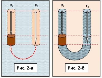
The boundaries of equipotential surfaces are drawn speculatively (reference system) through the lower and upper surfaces of the float, corresponding to the radius-vectors of the action of the planet's gravitational forces on the masses of the float and liquid.
Archimedean force is the resultant forceF A double pressure force, bottomF 2 on the base of the float and on topF 1 to the surface of the float.F A= F 2 – F 1 .Pressure force F 1 and F 2 each is proportional to the weight of the fluid, that is, the WORK of the gravitational forces (F gr ) "each for its own column" of liquid. By "pillars" we mean the columns of hydrostatic pressure forces shown in the figures.
What conclusions can we come to by comparing schemes 1-a, 1-b and 2-a, 2-b?
In figure 2-b in U -shaped communicating vessel, the law of Archimedes is carried out in strict accordance with the scheme of the mechanism of action of the lifting Archimedean forces shown in Figure 2-a, when the "pillars" of the liquid mass are precisely inscribed in the capacity of the left and right branches of the communicating vessels. Scheme 2-brass is considered as an analogue of the scheme of hydraulic balances 1-b and shows full compliance with the mechanisms for the implementation of natural physical effects “communicating vessels” and “lifting Archimedean forces”.
The law of action of the Archimedean lifting force can be considered as a special case of the law of communicating vessels and vice versa.
Let's ask ourselves one more question. The answer to it for the inventor of the "perpetual motion machine" determines the real prospect of his perseverance. What are energy sources for the operation of the mechanism of action of the lifting Archimedean forces on the float in the left branch of the communicating vessels in Fig. 2-b and for the operation of the mechanism for maintaining the liquid level in the left branch of the communicating vessels in Fig. 1-b?
From a comparative analysis of the mechanisms for the implementation of the natural effects "communicating vessels" and "lifting Archimedean forces", considered in the figures, it obviously follows that SUCH a source of energy, ultimately, is the WORK of gravitational forces in right branches of communicating vessels, transmitted in left a communicating vessel through the force gradient mechanism (see the diagrams for the equipotential surfaces shown) of the hydrostatic pressure of the "pillars" of the gravitational mass of the liquid.
This conclusion is confirmed by the postulate of mechanics: "The mechanism of action of any force to move the working body can be realized only and only WHEN BASED is the counteraction of another force." The Archimedean force, figuratively speaking, "relies" as it were on the equipotential surfaces of the reference system, indicated in the figures by a red dotted line. This conclusion is important for subsequent reasoning.
As a result of our reasoning about the law of communicating vessels, let's ask the third series of questions and consider the principle diagram of the operation of a perpetual motion machine of the second kind, proposed by the inventor in Figure 3.

Figure 3 shows an oval tube placed vertically. We, as in previous examples, consider it as a system of left and right communicating vessels. Correction balls are freely placed in the pipe. The liquid is brought into the looped flow (counterclockwise) by some external drive.
Questions:
1. How will a change in direction affect c reference systems for the forces of gravity and the gradient of hydrostatic pressure forces on the result of the fulfillment of the law of Archimedes in the columns of fluid of communicating vessels under the conditions of vertical movement of fluid in communicating vessels in the gravitational field of the planet, when it rises by inertia upwards and when it falls under the influence of its weight downwards?
2. Will the well-known the physical effect of DRIVING the fluid upwards well-known water-lifting device of the type " airlift»?
VD Inventor Answers:
The magnitude of the gravitational force on the control mass changes during its vertical movement along with its reference frame.
The flow “falling” in the left pipe approaches weightlessness and the absence of Archimedean forces, and the overload “taking off” by inertia acts on the flow and the Archimedean forces increase, therefore, under the conditions of vertical movement of the liquid, the inequality of the action of these forces arises and their work is realized to drive the mass of liquid into a unidirectional flow counterclock-wise.
According to the formula of the law of Archimedes on the magnitude of the lifting force of the float, whereg\u003d 9.8 m / s 2 free fall acceleration; a- acceleration of the external force of the drive (starter) of the liquid into the flow through the looped pipe; mis the mass of the volume of liquid displaced by the float(s).
F A = mg, when the fluid is NOT moving relative to the planet's gravitational field.
F A left \u003d m (g -a),when the liquid moves relative to the planet's gravitational field in a downward flow.
F A right \u003d m (g + a),when the fluid moves relative to the planet's gravitational field in an updraft. Then:
m (g-a) < m (g + a); F A left< F A is right.
After the initial acceleration of the liquid along the annular pipe (communicating vessels) by some external drive and then, at the moment of its shutdown, the value of the lifting force of the floats is considered as the force of the AIRLIFT-DRIVE of the liquid into the flow (by analogy with the principle of operation of the water-lifting devices "airlift", where the floats act as pistons to drive the upward flow). This drive force, according to the law of Archimedes and the law of communicating vessels, will be determined by:
F A drive = F A right - F A left = m (g + a) - m (g - a).
Note: The same method of proving the efficiency of the Archimedean motor-motor (drive) in the variant for Archimedean forces in a gravitational field is applicable to the Archimedean motor-motor (drive) in the variant of Archimedean forces in the field of centrifugal inertia forces. I used the second version of the drive scheme by the work of Archimedean forces in the invention, p patent of the Russian Federation No. 2396681 dated 10.08.2010 "Electromagnetic hydrodynamic generator (EMGDG)". I will boast here of only the expected picture of its future appearance.
Literature :
1. Bogomolov V.I. Patent of the Russian Federation No. 2396681 dated 08/10/2010 for "Electromagnetic hydrodynamic generator (EMGDG)" http://khd2.narod.ru/authors/bgmlv/bgmlv.htm;
2. Bogomolov V.I. M-paradigm of physics. .
3. Zuev V.V. "Energy Density, Properties of Minerals and the Energy Structure of the Earth" - St. Petersburg: Nauka, 1995 - 128s.
From a letter to E. Arsentiev
Hello Eugene!
I got sick for half a winter, read science fiction. For fun, I thought about an alternative history in which steam engines for ships could have appeared a couple of thousand years earlier.
This is where the schema came into being. Its specificity is that the higher the vertical "power" pipe "airlift" of the fluid drive into the stream, the greater the efficiency of the Archimedean steam engine. Therefore, part of the structure must be placed not only in the hull, but also in the keel, such as on a yacht.
About the principle of operation of the Archimedean engine according to my RF patent for the EMGDG electric generator (which, unfortunately, no one has been interested in for a year now!) I wrote an article on one page “What else does the law of communicating vessels tell us about?”.I attached a file to the letter. The material can help the DIY enthusiast figure out when building a model of such a yacht.
Sincerely, Vyacheslav
Steam Archimedean engine-airlift Bogomolov
with Arsentiev vortex jet for yachts

To the non-renewable fuel energy spent by the user for the operation of the steam boiler are added two sources of free renewable energy from the environment:
1. Formed by a steam boiler in a vertical pipe steam bubbles and convective currents add power to the device by the work of Archimedean forces in the upward flow through the pipe upwards, and thus act as pistons for driving the steam-water mixture into the flow through the pipeline to the water jet. At the same time, there are no Archimedean forces in the downward flow down the pipe and do not slow down the flow. Thanks to the converging helix-shaped pipeline, the flow velocity increases as it approaches the nozzle.
2. Steam-water mixture through the nozzle injected into the jet vortex former as a hot and expanded working fluid. The formed toroidal vortex is constantly replenished with a hot flow of the working fluid from the device, on the one hand. And on the other hand, as a result of constant cooling and adiabatic compression of the working fluid, is replenished ejected outboard water under the free accompanying pressure of the medium at depth. The work of the forces of deep pressure adds power to the propulsion engine.
3. The absence in the scheme of unnecessary units-energy converters from one form to another, the absence of mechanical gearboxes and moving mechanical parts increases the efficiency and reliability of the device.
N.B.: I believe that the stated fundamental possibility of hardware utilization of the energy of the free work of the forces of the planet's hydrostatic pressure in the scheme of a steam jet engine-propulsor of a vortex water jet is similar to the "implosion" principle of V. Schauberger.
There is an additional idea. The role of a furnace and a steam boiler inside the airlift pipe can be performed by a water electrolysis device with a high-voltage pulsed arc right inside the airlift pipe and immediately burn the bubbles of the resulting hydrogen-oxygen mixture (microexplosions), and thereby generate steam bubbles in the power pipe. As a result of electrolysis and microexplosions, the liquid in the pipe will be ionized, and then, as an electrically charged working fluid, it will be possible, in addition to vaporization, to use, according to the idea of my EMGDG patent, in generating electricity by a magnetohydrodynamic generator for subsequent re-feeding of the voltaic arc ... This will be the third way to add the power of the steam Archimedean engine with a vortex propeller-water jet.
The electro-hydraulic effect of L.A. Yutkin (hydraulic explosion with a spark), used as a “jet thrower” (“YuT” 1957), is immediately acceptable
Attached is a variant of the scheme of the internal combustion steam engine.
Steam "boiler" on gas.
(Options: hydrogen + oxygen; propane + air)

A simple automatic system of gas ejection into the combustion chamber for a cyclic explosion of the working mixture. The prototype is a two-stroke operation of the internal combustion engine.
The first portion of gas for the formation of a combustible mixture in the combustion chamber when the engine is started is pumped manually forcibly by a pump under pressure, then its explosion is initiated by an electric discharge (spark, arc). , already without the participation of an external pump.
After the explosion in the chamber, part of the steam-water mixture is injected into the airlift pipe by an impulse, and the vacated volume in the chamber, therefore, according to the law of communicating vessels, is occupied by water from the airlift pipe. This water compresses the combustible mixture formed in the working chamber under pressure, according to the principle of an air bell, in accordance with the depth of the air bell into the reservoir. Immediately, the next ignition of the working mixture occurs automatically.
In such a simple design scheme "internal combustion steam engine" the most difficult for handicraft production will be to achieve the tightness of the pipeline along with the combustion chamber and the quality of the gas valves.
Reasoning on the topic of physical effects in the operation of the Clem engine
(But not about the details of its design!)
Let's do some speculative experiments.
Imagine a tube AB filled with liquid. Consider two possible mechanical way to move a liquid through a pipe. This is: gradient difference pressures in the structure of the substance of the liquid along the pipe and mass inertial force liquid substances.

If the tube is fixed on a rotating shaft so that it becomes a generatrix of the side surface of the cone, as in Figure 1 (let's call this design "rotor"), then under the action of centrifugal force (CBS) we can observe the above methods DRIVE liquids into the stream. To implement these methods, you need to create some sufficient conditions , because these methods are not always implemented in the field of centrifugal forces.
1. If end hole AT pipes closed(the condition for the realization of the effect), then in the pipe under the action of centrifugal forces a radial pressure gradient in a liquid with maximum pressure at a point AT. (no DRIVE)
2. If the holes are equal in area and open, then the CB will not create ADDITIONAL pressure, but another condition will arise for the implementation of the drive into the flow by inertia.
If the holes of ends A and B of the pipe open, and there is freedom to move the mass of matter under the action of the centrifugal force of inertia, then the liquid will move radially through the pipe, rushing from point A to B. If hole A is lowered into the vessel (open to the atmosphere), then the liquid from the vessel will be pumped from bottom to top according to the design principle of a centrifugal pump (there is a DRIVE). In this case, both methods (pressure gradient and centrifugal force) are involved in bringing the fluid into motion.
3. If ends A and B of our pipe are connected to each other by another pipe in the form of a looped pipeline (rotating TOGETHER with pipe AB), then the mass of liquid will NOT move through the pipe, because in a looped pipeline, two opposite pressure gradients will be created, compensating and inhibiting each other. The centrifugal force in the pipe AB will not be able to move the substance, because there is no freedom (there is no DRIVE).
4. If the specific design of the virtual experimental stand (Fig. 2) allows the AB pipe (rotor) to continue ROTATION in the LOOPED pipeline, but the pipe connecting the ends will be fixed STILL(let's call this design "stator"), then other specific conditions implementation for the movement of fluid under the action of the CBS, namely: as in the case of figures 1 and 2, the mass of fluid will move radially along the pipe, rush upward from point A to B (there is a DRIVE of the “centrifugal pump” type).
Why? Because, unlike the conditions of paragraph No. 3, in THIS looped pipeline WILL NOT be created counter pressure gradients compensating each other, since gradient there will be no pressure at all, similar to the scheme of point No. 2. A single pressure equal to maximum pressure at point B. Why? Because, according to Pascal's law, the liquid transfers uniformly the maximum pressure from point B throughout the entire closed pipeline, if the cross-sectional area of the flow through the pipe and the flow velocity are the same everywhere in the pipeline.
Thus, our stand began to work, firstly, as energy accumulator, not only the kinetic energy of rotation of the liquid mass, but also the kinetic energy of the translational flow of the liquid mass. At the same time, the speed of the flow produced by the work of the centrifugal DRIVE will increase under the action of the CLS until this work is compensated by the work of the hydrodynamic resistance forces in the pipes. Accordingly, the energy of the work of the friction forces will be converted into thermal energy, and the stand will, secondly, also work as a heat generator.
5. If by any means in the experimental setup (Fig. 3) we additionally insert a turbine into the circuit in the STATOR section, then we will force the liquid to move in the opposite direction along the VA rotor, with a force greater than the force of centrifugal forces, because in accordance with the energy expended for the operation of this EXTERNAL drive, the Coriolis inertia forces will be self-roll rotor.
We will assume that self-rolling the rotor is the purpose of the design of the Clem machine. It is unlikely that jets of nozzles perform this function. I think not nozzles, but nozzles are needed only to cool the liquid.
6. Let's consider another design technique (besides the external drive turbine example) HOW force move the liquid in the opposite direction along the pipeline. counteracting operation of the DRIVE of centrifugal forces of inertia, which means with a force greater than the force of centrifugal forces.
To do this, part of the looped flow in the section BA of the rotor REPLACE channel according to the scheme of the well-known mechanism "Archimedes' screw". It converts the rotational motion of the screw into the translational motion of the fluid. It is this forward movement of the flow through the Archimedes screw that will create the reverse flow direction in the entire looped pipeline, which is larger in magnitude and counteracts the centrifugal forces of inertia of the mass of the rotor liquid.
Instead of the AB tube, we use the AB channel, let's make the ROTOR like an Archimedes screw in the form of a cone with a spiral channel, like a similar part in the Clem machine. The cone screw will create a high LOCKING pressure at the tip of the cone to counteract and defeat the centrifugal force.
What did we get with such a scheme of our speculative experimental stand? Wasting energy external drive to rotate the rotor, the device implements at least two physical effects:
A) Centrifugal forces of inertia are created and the work of these forces creates high pressure in the looped pipeline as a whole. I draw attention to the postulate advocated by me, namely, to Effect the phenomenon “pressure in a liquid” arising here, as a phenomenon of the existence of a stored FREE energy during the rotation of the mass of fluid in the rotor-flywheel. Why for free? Because this pressure energy can be utilized in any way by the consumer for free, and after that, by braking the rotor, it is possible to recover all the kinetic energy of mass rotation accumulated by the flywheel, which was expended by an external drive during the spin-up of the flywheel. The reference to the recuperation of the kinetic energy of rotation proves the gratuitous nature of the occurrence of pressure in a liquid in the field of centrifugal forces. One way to use the gift of pressure energy is to rebuild the internal structure of a liquid.
B) Coriolis inertia forces are created, converting the WORK and energy (for now, let's say, the EXTERNAL source of any drive) by the radial displacement of the fluid mass into the WORK of the rotor drive into rotation and the kinetic energy of rotation of the rotor fluid mass. And also, the work of the Coriolis forces also creates additional pressure, "locking" the opposing flow created by the WORK of centrifugal forces.
7. Where to get free energy and how to form such a countercurrent head to the pressure generated by centrifugal forces in order to form a decent speed of movement of the fluid mass from the periphery to the center of the rotor (from point B to point A) and, thus, “decent” Coriolis forces capable of “decently” self-promotion rotor?
Pay attention to such specific parameters that will appear in the device according to the Clem scheme when it is started (promotion) by an external starter. Instead of the AB pipe, we used the channel of a cone screw, made according to calculations of such a shape that the pressure created by the forward movement of the flow would be “decent” b about greater than the flow pressure created by centrifugal forces. And this means that in the spiral channel, in the flow from B to A, such a parameter as “high pressure” will be formed. To create a "decent" rotor speed due to the work of Coriolis forces, the fluid flow rate through the channel must be large. When moving through a liquid channel at high speed, “decent” forces of hydrodynamic resistance and just friction will arise - another acquired parameter of the liquid as a working fluid and working body in our device.
What can such acquired parameters of liquid give us at this stage of reasoning and speculative experiment? Together they MAY create the conditions for restructuring liquids .
8. We would be very pleased if the liquid pushed through the channel by the Archimedes screw would also expand when heated, increasing in volume in this section of the channel! If the powerful molecular forces stored by the substance came into play, and this “reactivated” energy source would help us create a “decent” flow pressure in the direction from B to A, then we could predict that after the starter spins up to a certain rotor speed , then the rotor could continue its independent rotation due to the internal energy of the fluid.
What will it be lean the force of an expanding fluid acting as the DRIVE of a mass of fluid into the flow, counteracting the DRIVE with centrifugal force to redirect the flow in the opposite direction? A force can only rely on another force - the law of mechanics. The answer is this. The expanding liquid will expand towards the direction of the flow VA formed by the Archimedes screw, leaning on the force of the impulse VA from the Archimedes screw, on the force of inertia of the mass of the ALREADY PREVIOUSLY FORMED flow by the Archimedes screw.
There are liquids that "decently" expand when heated. Clem used sunflower oil as a liquid working fluid. Hydrodynamic resistance and friction are guaranteed to heat the liquid to a high temperature. Heating under pressure moves the temperature boundary, the measure of its phase transition, boiling, further increasing the expansion volume of the superheated liquid. It can be assumed that with such parameters cavitation may occur and, perhaps, it will also contribute to an increase in pressure ...
9. Accordingly, heated in one cycle (cycle) of movement in a closed system, the liquid, before starting a new cycle, must be forced to cool . For example, first spraying through the nozzles, and then passing additionally through the cooling radiator. And if in the Clem motor, like a steam engine, a cyclic rearrangement of the structure of matter is initiated when it is heated and expanded, if this releases the internal energy of the liquid, which is capable of turning into mechanical energy of rotation of the rotor, then (!) Nobody canceled the law of the Carnot cycle.
10. But then the question remains, where is the source of free energy, due to which, in the end, expanding, the liquid rotates the rotor? My answer. The source of free energy here is the PRESSURE created by the GIFT centrifugal forces of inertia.
Statement of the hypothesis . The technical solution that ensured the operability of the Clem motor is achieved system successively (“loopback”) realizable physical effects:
In the field of action of centrifugal forces in the channel of the Archimedes screw, free pressure arises (and Coriolis forces arise);
Mechanical work of pressure forces, flow velocity and friction in the channel heat the liquid;
The liquid heated in the channel expands and makes b about greater work of the DRIVE of the mass of liquid into the flow than the work of the DRIVE of centrifugal forces opposing it;
The work of the fluid flow on the radial movement of the mass from the periphery to the center (path VA) by the Coriolis inertia forces self-unwinds the rotor-screw of Archimedes;
The self-rotation of the rotor generates a field of centrifugal forces and the work of the Archimedes screw, and, most importantly, the expanding fluid sets the flow through the stator channel in motion to repeat a new cycle of the looped fluid flow in the device;
The flow of liquid through the cooling radiator in the stator creates the conditions for the Carnot cycle for heat engines.
Thus, the source of energy for the operation of the Clemas engine is two natural physical effects, namely: free pressure in the field of centrifugal forces in the rotor and free cooling of the liquid by the external environment in the stator. Compressing adiabatically during cooling, the liquid can form a “suction” of the flow from part of the rotor channel into the stator channel, generating additional engine power.
The Clem engine system is not closed, it carries out thermodynamic and inertial energy exchange with the environment and utilizes part of the free energy of the environment during this energy exchange.
Description of the invention
"Bogomolov Generator - Converter (GB-K)"
Definition of invention, its purpose .
The device "GB-K" is intended for the consumer to receive electrical energy in the form of direct current. Refers to power plants using alternative energy sources of renewable natural resources.
The design of the device is a system, a complex of two open systems, mechanical and electrical. These are open (not closed) systems connected with the environment by energy exchange and drawing energy from it, as well as all other known alternative power plants, solar panels, windmills, hydroelectric power stations.
Since the “AK” device is an open system, its operating principle does not violate the law of conservation and transformation of energy, therefore, the “AK” device cannot be classified as “perpetual motion machines of the first and third kind”, theoretically impossible devices in principle!
"GB-K" differs in that in it as alternative energy source renewable natural resources the free energy of the environment of physical vacuum is used in the form of free work of centrifugal forces of inertia, which is converted by the device into electrical energy.
"GB-K" is a modified "GB-1998".

Figures 1a, 1b and 1c show " pneumohydraulic centrifugal speed controller (TsRS)» for GB-1998. The design of this unit, in accordance with the laws of conservation of kinetic energy of rotation and angular momentum, provides in technology automatic adjustment of mechanisms to maintain a constant rotation speed. The prototype of the invention "pneumohydraulic CRS" is a lever "Watt centrifugal speed controller" (Fig. 2).

The CRS (Fig. 1a, 1b and 1c) consists of a one-piece body-rotor with chambers for liquid mass: a cylindrical (along the axis of rotation of the rotor) chamber and a lenticular chamber. An elastic balloon filled with pressurized gas is placed inside the lens-shaped chamber. It acts as an air spring. The rest of the space is filled with a heavy liquid.
In device " Bogomolov generator 1998 (GB-1998)"(Fig. 2b) the centrifugal speed controller (Fig. 1a, 1b and 1c) performs the main function generating free kinetic energy of rotation (mechanical energy) in the mode of cyclic acceleration and deceleration (author's know-how). In the “GB” device, the TsRS as a flywheel is located on the same shaft with a reversible electric machine “motor-generator” (Fig. 2b). During cyclic operation in the acceleration cycle, the CRS is generated by the electric motor, and the flywheel accumulates the energy of the free work of centrifugal forces; in the braking cycle by the resistance of the electric generator under load, the electric energy spent on the spin-up of the flywheel-CRS by the electric motor recuperated, and the incremental free mechanical energy of the CRS flywheel is converted by an electric machine (generator) into free electricity.
In the modified device "GB", in the device "GB-K"
the “pneumatic-hydraulic centrifugal speed controller (CRS)” unit has been structurally modified for an additional function (plus the function of generating incremental mechanical energy), namely, for its own generation of free electricity. The CRS unit turns its own mechanical work of the flywheel into an electrical potential, increases the voltage in the circuit according to the principle of operation (prototype of the invention) of a well-known type of device - an electromechanical "converter", a capacitive converter (transformer) (Fig. 4).

The TsRS (Fig. 3a, 3b and 3c) of the GB-K device consists of a solid body-rotor with chambers for liquid mass: a cylindrical (along the axis of rotation of the rotor) chamber and a lenticular chamber. An electrically conductive liquid moves freely inside the chamber.
Figure 3a shows the CRS without a liquid working fluid. Figure 3c shows the position of the liquid electrode (green color, working fluid) at the beginning first cycle of operation of the CRS as a converter. Figure 3b shows the position of the liquid electrode (green color, working fluid) at the end second tact of the CRS, as a converter.
The principle of operation of the prototype converter of the invention.
(See help at the end of the article)
In a typical mechanical converter low input voltageU 1U 2, while the output current and input current are the same. The output power exceeds the input electrical power. This physical transformation effect (the effect of electrostatic induction) is carried out due to the energy consumption of an external drive for mechanical work in moving apart (moving) the plates of a capacitor of variable capacity, chargedU 1at the minimum distance. When the electrodes are moved to the maximum distance, a higher output voltage is achievedU 2.
The device and principle of operation of the converter-unit TsRS VGB-2011 differs from the prototype in that:
The variable capacitance capacitor with plate electrodes has been replaced with an analogue of the "Leiden jar" type capacitor, which has a central rod electrode and a second electrode-plating on the periphery of the vessel. The role of the vessel of the Leyden jar in GB-2011 is performed by the working chamber of the CRS;
The movable solid-state plate-electrode of the prototype variable capacitor was replaced in GB-2011 with an electrically conductive liquid. The liquid electrode can move freely from the central part of the working chamber to its periphery.
The principle of operation of the TsRS converter in the GB-2011 (GB-K) device.
In the first beatcyclic operation of the converter, with the acceleration of the CRS, under the action of centrifugal inertia forces in the CRS chamber, mechanical work is performed to remove the charged voltage from each otherU 1 electrodes.
Radial movement of the liquid electrode from the central rod electrode to the periphery of the chamber, as a capacitor of variable capacity, is achieved higher output voltage U 2at a finite maximum distance between the electrodes. In this position, the capacitor is discharged to the load by the value of the free electric energy incremented in the first cycle.
At the same time, as in the GB-1998 variant, in the GB-2011 modification in the first cycle of the CRS acceleration, free mechanical energy is produced and accumulated by the inertial mass of the liquid. In the version of the GB-1998 scheme, the mechanical energy of attraction of the mass of the liquid working fluid from the center to the periphery by the free work of the centrifugal forces of inertia was accumulated by a pneumatic spring. electrostatic field strength) Coulomb's attraction forces of the liquid-electrode mass to the central electrode of the capacitor.
In the second beatoperation of the converter, during braking of the CRS, the free work of attraction of the Coulomb forces, the liquid electrode returns to its original position of the minimum distance between the electrodes and the capacitor is again charged by an external energy source with a voltageU 1.The two-stroke cycle has ended, the converter is ready for the next cycle of operation.
At the same time, as in the GB-1998 version, in the GB-2011 modification, also in the second cycle "flywheel braking by the resistance of the electric generator under load", spent in the first cycle to spin up the flywheel-CRS by an electric motor, the electric energy of an external current source recuperated , and the mechanical energy accumulated by the fluid mass, incremented in the first cycle converted by reversible electrical machine(electric generator) through a common shaft with the central heating system (Fig. 4) free electricity.
In the variant of the GB-1998 scheme, in the second cycle, the mechanical energy accumulated by the pneumatic spring was expended on the displacement work masses liquid from the periphery to the center. In the variant of the GB-2011 scheme, the mechanical energy accumulated by the potential of the electrostatic field strength of the Coulomb is also spent on the work of moving masses fluid from the periphery to the center. In both versions of the "GB" scheme, the work of moving the mass of the liquid working fluid from the periphery to the center causes the effect of Coriolis forces along self-rolling flywheel-CRS.
In the version of the GB-2011 scheme, the mechanical energy accumulated by the potential of the electrostatic field strength of the Coulomb, the work of the Coriolis forces turns into incremental kinetic energy of rotation flywheel-CRS and, transmitted through a common shaft-CRS with an electric generator, the mechanical energy of rotation of the flywheel-CRS is converted into free electricity.
Thus, the invention "GB-2011-converter" (modification "GB-1998") generates the same amount of free mechanical energy of rotation flywheel-CRS, but more efficiently accumulates it and converts it into electricity. If in GB-1998 part of the energy received from the free work of centrifugal forces when it was utilized by a pneumatic accumulator was spent on heating the compressible gas (with subsequent radiation of this heat into the environment), then when the potential of the electrostatic field of the Coulomb force accumulates, the previously lost energy is now converted by the converter into EMF. Using the GB-K generator, the consumer receives the total amount of free electricity, jointly generated by a reversible electric machine and a converter.
Reference .
NB : In a specific GB-K design, a reversible electric machine can be replaced by a motor-generator unit that is more efficient in terms of efficiency.
A bit of theory about typical converters.
There are several types energy converters using the natural effect of electrostatic induction, which convert mechanical energy into electrical energy through capacitance changes charged capacitor. The energy reserve of a capacitor can be calculated by a simple formula: W=Q 2/(2C). From this relationship, we can conclude: if the capacitance of the capacitor C increases, and the accumulated charge Q remains unchanged (unchanged when the capacitor is disconnected from the power supply), the energy stored on the capacitor increases. That is, a mechanical device operating on this principle plays the role DC generator.
Changecapacitor capacitance mechanically possible in different ways. From the flat capacitor formula [ C=eS/d] shows that the capacitance depends on three quantities: permeability [ e] dielectric between plates, surface area of one side of one plate [ S], and the distance between the plates [ d]. By changing one or more of these parameters, it is possible to convert mechanical energy into electrical energy.

The figure shows a schematic diagram of the operation of the device, typicalmechanical DC converter, which is used for achieve a technical effect often used in industrial practice, a natural phenomenon, physical effect "electrostatic induction».
In a typical mechanical converter low input voltageU 1converted to higher output voltageU 2, while the output current and input current are the same, and accordingly, the output power exceeds the input electrical power.
In a typical rotary converter, when one rotor electrode is facing the ground segment at the bottom, they form a capacitor charged to a voltageU 1via bottom moving contactb 1. When the rotor turns, the charged electrode of the rotor opens with contactb 1and moves to the top position. This rotation is counteracted by the forces of attractionF rshown in the figure. When the charged electrode touches the top contactb 2, it is possible to extract the charge carried by it under the action of a higher voltage U 2, since the distance to the grounded electrode has increased and their mutual capacitance has decreased.
Power plant "Generator Bogomolov - Airlift
or water-lifting device (GB-E)"
I married the idea of forming gratuitous pressure ( rarefaction) centrifugal forces in the GB scheme with the idea of the DA (airlift) scheme of low-cost immersion of floats to the bottom, or low-cost work compressor airlift. Here GB-E acts as a compressor.
Recall the scheme of the "pneumo-hydraulic CRS" unit (see note about GB-K)

And let's recall the scheme of the Airlift power plant (with an engine that drives fluid into the flow through the annular pipe by the Archimedean Engine (YES), where an inductor is wound on the pipe or an MHD generator is installed). In this scheme blower(see in figure 2 the box "ejection of air into the falling stream") we will supplement " valve box"on the principle of the CRS unit on" GB ".

Proof of the operability of a LOW-COST compressor in the form of a GB scheme - This is the same, simple: a typical (always on sale) aggregation unit "motor-generator" in the cycle mode "braking by the load on the generator" is completely recuperates costs of external power supply in the acceleration cycle, in accordance with the laws of conservation of kinetic energy of rotation and momentum, even for a flywheel with mobile on the radius of the goods. In our case, these "weights" are liquid.
Another part of the proof of the efficiency of such a MIKST project (GB-E) is that the "theorem" of physics is no longer true here. By the theorem, the Archimedean forces (hydrostatic pressure) in the stroke of penetration ( sinking) floats (air bubbles) to the bottom (to the depth of the airlift pipe), supposedly, always with their work of counteraction resets subsequent useful work pop-up floats. And if the CRS unit “drowns” air bubbles (floats) for nothing? After all, electricity in the flywheel acceleration stroke is RECUPERATED almost completely work pressure at depth in the braking stroke by analogy with a spring cocked by centrifugal forces!
Yes, a GB-E device with the free work of Archimedean forces in a gravitational field will turn out to be large, but cheap! Firstly, for a cheap desktop experiment, it will do. Secondly, it will come in handy for deep wells, or for an offshore platform where, for example, oil must be pumped. Such a water-lifting device for pumping out is very useful. water with silt in sewage treatment plants or for lifting water from mineral breed from MINES. That is, everywhere where airlifts ALREADY work today, but they still work EXPENSIVELY. And we give them a cost-free climb up!
Even manufacturers of household submersible mini-pumps of the Malyutka type are obliged to be interested in the idea of GB-E!
Today there are reputable manufacturers of plastic airlifts for sewage treatment plants in Kharkov and the Crimea. These are our potential partners, they are financed by city administrations. Who will negotiate with them, negotiate about GB-E? I cant.
But, plus more! When using radial Archimedean forces, the option "from the centrifugal field of inertia to centrifuge" dimensions will be acceptable even for the motor car. The figure shows a rotating platform-centrifuge, and the white triangles will be the FREE compressor-valve boxes of the TsRS (from the GB-E scheme)
Here even the thrust of the precessional inercoid is visible! Like E. Linevich, maybe the car will not need an electric generator, but there will be a direct drive of its traction without driving wheels.

And so, the way of pairing the GB with the Airlift is essentially the transformation of the TsRS unit into a bypass valve box of air with atmospheric pressure to internal deep hydrostatic pressure. essence: in the acceleration stroke in the center of the chamber, the CRS is formed rarefaction for free. According to the design specifications, the vacuum in the CRS chamber is equal to the pressure at depth in the airlift pipe and is proportional to the rotation speed of the flywheel-CRS. This is a small angular velocity, technically achievable simply. essence: TsRS GB-E operates cyclically as a centrifugal pump(in the first measure)

Figure 4a shows an empty CRS chamber for "GB-E" with a system of liquid valves No. 2 and air valves No. 1 and 3

Figure 4b shows the “acceleration of rotation” cycle of the central heating system, a submersible compressor. The green arrows show the “unloading” of the chamber from water by the centrifugal forces and the filling with atmospheric air by the yellow arrow. essence: TsRS GB-E works cyclically as a centrifugal water pump (in the first cycle), and atmospheric pressure earns extra money for a hack, filling the space freed from water.

In Figure 4c, the “braking” cycle of the CRS, when the outboard water of the depth fills the chamber (green arrows) and by the Coriolis force it spins itself (the process of RECOVERY by the generator of the electricity spent in the first cycle by the motor), and also, FREE works as in standard scheme COMPRESSOR lifting device "Airlift", betraying the lens of air upwards into the airlift tube. (There are two principles of airlifts: either "foam" or "piston lenses".)
This is a preliminary sketch, just a principle. Maybe, as in pictures 1, you need to leave an elastic bag-pneumatic spring ... etc. An additional receiver-air bell may be required. This will be prompted by airlifters. Without airlift specialists, it’s better not to take on the model yourself, there is a delicate process: where is the foam, and where are the lenses ... But! I guarantee the operability of the free DRIVE of liquid into the stream! Cheap and angry.
Afterword to the selection of notes "Spring products 2011"
You looked through my notes with a description of the new schemes proposed by me this spring, allegedly super-unity devices, “perpetual motion machines of the second kind.” device system and the natural energy system of the environment.
As I stated in the preface to this selection of notes, in nature all the forces known to us are the result of the work of natural "machines", the work of mechanisms built by nature according to a single universal principle. Namely, the principle of continuous exchange energy in the environment, as a way of "automatic" restoration of the optimal energy balance as a whole, in cases of local violation of the parameter " energy density by volume » in radial energy density gradients of all known fields potential energy of conservative forces.
In the circuit diagrams invented by me, proposed to your attention, generators are used as sources of free natural energy. scheme devices of these "machines", designed by nature to implement the "automatic" alignment of the energy balance of the universe system in its subsystems, is identical and universal. In the densely packed material substance of the universe (the thin matter of the ether, the physical vacuum of the playful matter of material objects formed from this thin matter), there are local formations consisting of matter and force fields formed by them. It is customary to call such fields of forces "fields of potential energy", and these forces are "conservative forces".
According to the author, the unity of the schemes in the arrangement of all these natural “machines” lies in the fact that their “power unit” for the manifestation and implementation of the work of forces is the initially given principle of the radial gradient of energy density and mass of material substance by volume. In this "power unit", called the "potential energy field", we can mentally designate the equipotential surfaces of spheres of quantized energy density levels in the accepted reference frame.
In the schemes of artificial devices proposed by the author, the interaction of their own working bodies with the natural environment is carried out through the OPORA on gradient the density of the matter of the medium in the fields of potential energy: in the gravitational field of attraction of the mass of the medium, in the field of attraction of the mass of the medium by centrifugal forces of inertia, in the field of attraction of the mass of the medium by electrostatic Coulomb forces. These potential energy fields are formed by PRIMARY natural forces, and they, with their “power units”, create in the attracted mass of the environment substance SECONDARY natural forces, “returning” forces. It is through the work of the restoring forces that the "automatic" alignment of the energy potential of the systems is carried out, the redistribution of local flows of the universal energy exchange is carried out.
All circuits are built using the "AUM" algorithm proposed by the author of the "Universal Method" for designing superunits (SE). organize and redistribute energy exchange flows between the environment and the device in order to utilize part of the energy of this exchange.
AUM is bred as consequence from the author's version of "M-Paradigms of Physics".
AUM- organization of the process of invention (by analogy with TRIZ) and the design of schematic diagrams of devices for utilizing the energy of potential energy fields, - is formulated like this:
If two forms of potential energy of conservative forces are cyclically used in the device, the work of which has the opposite direction of action of the vectors, then it is LOW-COST, periodically turning off (weakening) the action of the field of the force form of energy and turning on (strengthening) the action of the field of forces of another form of energy, it is possible (!) In time and space to form positive difference powers of action of these forces to remove this power difference, i.e. to obtain useful power for the consumer of free energy. This is achieved by the inventor through the selection of known physical effects.
The use of AUM, the most general technique of the designer of CE devices, requires the author to make creative efforts in each specific scheme. low-cost disabling (weakening) the action of one of the natural opposing forces in the device.
So in the invention "EMGDG" (RF patent No. 2396681), the principle of operation of which, incl. discussed in the first note "What else ...", low-cost the method of "sinking" floats (weakening of Archimedean forces) is found in the physical effect: "The value of the force of gravity on the control mass changes during its vertical movement along with its reference frame."
The same is true for the EMGDG variant in the field of centrifugal forces, where "the magnitude of the force of action of centrifugal forces on the control mass changes during its radial movement along with its reference frame."
The same find is used in the “Archimedean steam engine-airlift” scheme, and in the “GB-E” scheme.
In Arsentiev's vortex water jet for an Archimedean steam engine, another way of increasing power due to the work of hydrostatic pressure forces was discovered.
In the hypothesis about the principle of operation of the Clem motor low-cost the action of centrifugal forces is weakened cyclically by the technical method of using the Carnot thermal cycle, which is achieved due to the cyclic use of the internal energy of the adiabatic expansion of the liquid and its cooling by the external environment.
In devices of the Bogomolov Generator family, GB-1998, GB-K, GB-E low-cost the method of disabling the action of centrifugal forces to generate free kinetic energy of rotation (mechanical energy) is achieved by setting the mode of cyclic acceleration and deceleration of the CRS flywheel unit. GB-This function is performed by deep hydrostatic pressure, these are also design methods for weakening (turning off) the action of one of the two opposing forces.
I would very much like to sum up with the words “what was required to be proved!”, But, unfortunately, without working models of the invented devices, all these “forewords” and “afterwords” remain so far “vanity”.
Winter has passed, summer has come, thanks to the party for this!
Chapter 4 Centrifugal Force
The Russian Patent Office, as you know, does not accept applications for a patent if it describes "movement due to internal forces." This is correct, but we must not forget that all bodies are in constant interaction and energy exchange with the ether, and the phenomenon of inertia has an etherodynamic nature. In this chapter, we will consider several simple solutions that allow you to get movement through interaction with the surrounding ethereal medium.
In Cassier's Magazine Volume 29, in 1906, several schemes were shown in which it is supposed to use the special geometry of the rotor to create an asymmetric internal pressure of a gas or other elastic medium that occurs when it rotates. Note that Louis Cassier in the period 1891-1913 (more than twenty years in a row) published interesting articles on the development of technology. Thanks to him, many of the ideas of the inventors of that time are now known to us. Free archives of his journal in English can be found on the Internet. The scheme shown in fig. 28, according to information from Cassier's Magazine, offered to the public in 1902.
Rice. 28. The rotor is filled with gas or other elastic medium
Each of the four body elements (beams) is equipped with a valve for pumping air or some gas into it. The device does not start to rotate on its own. To start, it must be rotated by hand. The author of this invention is not yet known to us. The scheme is very promising, and has no analogues in terms of simplicity of design.
Consider the conditions for creating torque. Let us assume that there is gas inside the four "beams" of the body, or another elastic working body, having inertial mass. Essential here is the factor of elasticity of the working fluid, which will be compressed unevenly under the action of centrifugal force. An incompressible fluid, in this situation, will not give the expected effect, since it will push in all directions with the same force. Elastic compressible working fluid presses on the housing unevenly, mainly along the radius of rotation.
The vector scheme is shown in fig. 29, where the presence of a tangential component is noted, which determines the rotation of the rotor of the machine.
Rice. 29. Scheme with the location of force vectors
From consideration of the vectors shown in fig. 29, it can be assumed that the compressible elastic “working mass” will press on the tangential sides of the body with more force than on the radial ones, which will create a torque and a constant acceleration of the rotor.
The operability of this scheme can be justified only by the presence in the surrounding elastic medium of a reaction to deformations of the elastic working body. In this case, the torque on the shaft of this device must be equivalent to the effect of "twisting" the surrounding ethereal medium in the area of operation of this device.
Let me change the circuit shown in Fig. 29, and offer more "beams", fig. 30. This is not important, but the "useful" surface of the hollow body, which creates the tangential component of the force, is increased in this design. I hope you are familiar with this Old Slavonic symbol of the Sun.
Rice. 30. Rotor with 8 beams
The device shown in fig. 31, is proposed by me for practical applications in the field of power supply and propulsion of aerospace systems.
Rice. 31. Frolov's rotor element. The axial and tangential components of the force are shown
In this case, one can expect the manifestation of not only the tangential component of the force, but also its axial component. The presence of an axial component makes it possible to obtain an axial driving (lifting) force.
On fig. 32 shows an embodiment of a rotor whose manufacture from a solid disk requires milling of triangular (in the simple case) cavities for an elastic and compressible "working mass". Of course, two more airtight lids are needed. It is possible to perform milling with an inclination with respect to the axis of rotation (according to the idea shown in Fig. 91), in order to obtain not only a tangential, but also an axial (lifting) component of the driving force.
Rice. 32. Rotor with cavity milling
Is this idea a fantasy of "propulsion by internal forces" or is it a practically useful technology? The question of the efficiency of the ideas shown in Fig. 28 - fig. 32 can be checked in a practical way, since these designs are simple, and there are a lot of options for choosing an elastic working inertial mass. It is proposed to conduct joint experiments, apply for a patent and start production of energy sources using this technology.
By publishing these ideas, I assume their successful commercialization, and preferably with my participation. Further development of the project depends on your production capabilities. To begin with, we need a small pilot plant to explore the main factors for improving this technology during development work, and find ways to optimally implement it in the mass production process. For more details, this and other projects are shown in my book New Space Technologies, 2012.
Let's move on to centrifugal machines with a jet effect, that is, analogues of the turbine of Heron of Alexandria. The scheme is shown in fig. 33. In the treatise "Pneumatics", about 120 BC, Heron described various machines driven by compressed air or steam due to the reactive effect. For example, Heron's "aeolipyle" was the first steam turbine in the form of a ball, rotated by the power of jets of water vapor emitted under high pressure from tangentially located nozzles.
Rice. 33. Turbine of Heron of Alexandria
The Heron turbine uses steam pressure, like modern steam and other gas turbine machines on which modern energy is based. "Steam pressure" - these important words sit firmly in the minds of all power engineers and locomotive drivers. To create pressure, you need to heat the water, that is, burn gas, coal, fuel oil. then the turbine of the electric generator will rotate. Gentlemen of energy, you are being deceived! Pressure, as a result of centrifugal force, is created without fuel, almost for nothing! This has been known for thousands of years, but you have not been told it. or you forgot it.
Around 1760, an engine based on the jet action of flowing water was invented by Johann Andreas von Segner. (Johann Andreas von Segner). Segner did not set himself the task of obtaining an autonomously working machine. He applied the method of using centrifugal force to accelerate the rotor of a water mill - a machine that produced useful work when a stream of water was supplied to it from the outside. However, the essence of his idea is that the power of the machine depends not only on the kinetic energy of the water flow. In such a machine, any jet pressure at the outlet can be created, since it increases with an increase in the rotor speed: centrifugal force accelerates the working mass, and creates the effect of negative pressure (vacuum) at the flow inlet to the rotor. The pressure drop is growing. This causes excess power. Many proposed centrifugal machines are based on the general principle of the "Segner wheel". The mode of self-rotation of the “modernized” Segner wheel can be simplistically imagined as shown in Fig. 34.
Rice. 34. Segner rotor. Water enters through the axis of rotation
Important nuances. First, provided that sealed system, and water enters the rotor on its own due to the pressure drop, and is not pumped by a pump, such a rotor will self-accelerate as long as water enters it. In the center, along the axis, the water flow moves at a lower speed than at the outlet, so the pipe cross section at the inlet must be greater than the total cross section of all nozzles. Note that in addition to torque, a pair effect is created in the design - axial thrust.
Another constructive subtlety - working fluid must be compressible. The algorithm includes phases of compression due to centrifugal forces and expansion, while additional kinetic energy arises in the system due to the release of the potential energy of compression. We can use the increase in the kinetic energy of the flow on the turbine impellers or in another way. To fulfill these conditions, it is necessary to allow the water to accelerate during movement due to the influence of centrifugal forces. Theorists call the optimal trajectory of its movement a logarithmic spiral of variable radius, shown in Fig. 35.
Rice. 35. Logarithmic spiral
Some modern centrifugal pumps and fans already have just such a design of the blades or the trajectory of the movement of the working mass, so they are very efficient. In a simplified version, the movement of a mass of water along a flat or conical spiral with any increase in radius gives the water the ability to accelerate and create additional torque for the rotor.
Perhaps the use of air as a working mass will be easier, but it is much lighter, so the rotation speeds will be much higher, and this will require high-quality manufacturing of rotating machine parts and processing (polishing) of the body. Theoretically, everything is not very complicated.
Let's consider the most famous and reliable example of the implementation of a technical device operating in accordance with these principles: the Clem motor, which uses centrifugal force for self-rotation. In 1972, Richard Clem worked as a heavy equipment operator in Dallas, USA. He noticed that a conventional hot asphalt sprinkler continued to rotate for another hour after its drive was turned off. The axis of such a machine is vertical, and the rotor has a conical shape. Klemm did not know the theory, he began to study the issue empirically, and built a self-rotating "Clem motor". On fig. 36 shows a schematic diagram of such a generator that can use centrifugal force to move a liquid mass along a conical expanding path.
Rice. 36. A variant of the circuit diagram of the Clem generator
This is not Clem's original scheme, but a variant of the constructive execution of his idea. On fig. 37 shows another schematic diagram of this design. The conical rotor is placed in a conical housing and has spiral channels cut into it. These spiral paths run along the cone and end at its base in the form of nozzles (nozzles). The recommendations of theorists and practitioners for the creation of similar structures are that it is necessary to “give the liquid the opportunity to root”, since centrifugal force acts on it.
Rice. 37 The principle of operation of the Clem drive. Design option
To do this, the spiral should have an increase in pitch with increasing radius, and it is also desirable to increase the cross section of the channel through which the liquid flows, as it approaches the nozzle. This is not noted in the articles about the Clem engine, but is assumed theoretically.
The spiral tube along which the working liquid mass moves, which has an increase in pitch and cross section as the radius of rotation increases, is called the “antelope horn”.
There are several factors here. The point is not only in the reactive Segner effect. The acceleration of the fluid moving in a spiral, interacting with the rotor, leads to the fact that it transfers the torque to the rotor. At the entrance to the rotor, the speed of the liquid is equal to the speed of rotation of the rotor. In the section of the trajectory in front of the nozzle, the liquid moves faster than the rotor (the increase in speed is due to the centrifugal effect). Thus, the rotor accelerates, and at a certain rotation speed, the external drive can be turned off, and the machine switches to the energy generator mode. For optimal use of the kinetic energy of the jet after exiting the nozzle, it is advisable to use inclined reflectors in the design - the blades of the turbine impeller.
Thus, in this design there are three key aspects:
1. The reactive Segner effect speeds up the rotor.
2. The acceleration of the fluid, if it is possible to increase the radius of its movement under the action of centrifugal force, leads to the fact that it moves faster than the rotor, and gives it an additional torque.
3. The reactive interaction of the mass of water, which has already flown out of the nozzle and “works” with the turbine impeller fixed on the rotor, additionally accelerates its rotation.
Richard Clem built a machine that used Mazola edible olive oil, as the liquid during operation was very hot (up to about +150 degrees Celsius), and the water boiled. Perhaps oil must also be used because this liquid has a greater elasticity than water. In Clem's actual design, fluid was injected into a hollow shaft at pressures in the range of 300–500 psi (21–35 kg/cm2), passed through the cone's tight helical channels, and exited through nozzles. This caused the cone to rotate. The shaft rotation speed in Clem's design reached 2300 rpm. To cool the working fluid, a heat exchanger (radiator) was used.
It is known that the first motor could not withstand the loads, and collapsed. Clem made the second version of the engine more durable. In this version, the motor had a power of approximately 350 hp. and weighed about 90 kg.
Richard put his motor on the car, and demonstrated his work on trips. The battery was used only to start the engine and the headlights of the car. According to the author of the invention, the power plant "consisted of a seven-stage pump (seven stage pump) and a converter." The pump, as the author described it, was used to "supply oil under pressure from storage to the converter, where the energy was converted into force sufficient to rotate the motor." The oil returned to the tank, and the cycle of movement of the working fluid continued again. The converter, that is, the energy converter, acted like a turbine, but "was not a turbine in the usual sense of the word," as Clem said.
Rice. 38. On the left in the photo: details of the original design. Right - computer model
The inventor sought support in financial and industrial circles, easily convincing them of the benefits of this technology. He once said that if the automobile industry accepted his new invention, drivers could only change the oil in his engine every 150,000 miles, but never buy gas in between.
Clem's engine was tested by the Bendix Corporation. The test consisted of connecting the engine to a dynamometer to measure the power generated by the engine in self-rotating mode. He steadily gave out 350 hp. for 9 days in a row, which amazed the Bendix engineers. Then, Richard Clem received a serious order from the coal company for the manufacture of several powerful machines, but died suddenly of a heart attack.
Details of the history of this invention are available on the KeelyNet page of Jerry Decker. The address of his site is familiar to me for a long time, I recommend you for a detailed study of the topic: www.keelynet.com
The theory of mechanical centrifugal machines capable of operating in the self-rotation mode requires serious study. In general terms, we can say that centrifugal force and other inertial effects belong to the field of etherodynamics. Inertia is a property of the environment surrounding the body. These are external forces, not internal forces of a closed system. Similar to aerodynamics, in the presence of a pressure gradient of the medium, in such an open system, a driving or lifting force is created, and in some cases, both components.
In the simplest version, the centrifugal force creates an increase in the potential energy of the body, without spending power from the primary source, and the task of the designer is not only to “free” the working mass and allow it to move along the line of action of the centrifugal force, but at the same time, to effectively use its kinetic energy.
This topic is very promising, since, with serial mass production, such machines can become widely used simple, reliable and inexpensive energy sources. At present, in 2012, we are working on the creation of a centrifugal-vortex energy converter. Based on the Schauberger engine. A research report is ready with power calculations, and a set of documentation for the manufacture of a 30 kW drive. Details on the website www.faraday.ru and http://alexfrolov.narod.ru
Consider no less famous than the Clem engine, and earlier in time, a self-rotating Schauberger energy generator. It is not our task to consider ways to create an active (non-reactive) propulsion force, which is used in aircraft designs. We will consider the inventions of Viktor Schauberger only as technical solutions that are practically useful for the development of new energy sources. However, we note that both components of the driving force (axial and tangential) make it possible to use such a machine both as an energy source and as an active (non-reactive) propulsion device for an aircraft or other transport, for example, for aviation, sea, river, road or rail transport.
The history of the inventor Viktor Schauberger is very interesting, especially because he found all the principles of his machines in observations of Nature. His main place of work is forestry in Austria, where he developed agro-technical technologies, reflected in his patents.
The general scheme of its installation is already familiar to us from the works of Clem. The version of the machine shown in fig. 39, left, suggested by Leopold Sheriju. It is known that it was not implemented because it has flaws. Agree, the scheme is very similar to the design of Richard Clem, but Sherju does not have a cone rotor. In my opinion, this shortcoming is critical. The rotation of the fluid creates a centrifugal force, which we must use to increase the kinetic energy of the working fluid. To fulfill this condition, the radius of rotation of the liquid must gradually increase, preferably along the trajectory of a logarithmic spiral, which makes it possible to increase the radial component of the liquid velocity due to the influence of centrifugal force.
Rice. 39. Schematic diagram of the Leopold Sherzhyu generator (left) and Frolov's centrifugal machine (right)
This solution is proposed in Fig. 39, right, Frolov's design, 2011. Currently, the project to create a workable Schauberger generator is developing, and we invite interested investors and production partners to participate in the project.
I wonder if Richard Clem knew about the work of Viktor Schauberger? This seems unlikely, since Richard worked as a simple operator of heavy equipment, in particular, a hot asphalt sprinkler. Most likely, these two inventions are two independent projects, when considering which, it is useful to find analogies and draw conclusions for the design of machines of this type.
Photos of the original Schauberger device, which is kept in a museum in Austria, are published with the permission of the Schauberger family, their website www.pks.or.at In fig. 40 shows the author and his "home generator". Water enters from above, in the narrow part of the cone. It should be noted that, in addition to water, there is always a small amount of air in the tubes, and this condition is considered as necessary for the successful operation of the device. The photo shows a ball-shaped air filter. When setting up the machine, it was important to select, with the help of valves and control taps, the required combination of water and air in the tubes.
Rice. 40. Viktor Schauberger and his "home generator"
At the bottom left is an electric generator and a pulley. The rotor is made of copper tubes that wrap around a cone, as shown in the photo in fig. 41.
Rice. 41. Device in the Schauberger Museum, Austria
The aerated liquid has elasticity, which allows it to accumulate potential energy when the liquid is compressed under the action of centrifugal forces, and then convert it into the kinetic energy of the rotor. We have already noted this nuance: the elasticity of the working fluid, in such designs, is necessary for the conversion of potential energy. Centrifugal force compresses the working mass, it increases the potential energy. Further, when moving in a spiral with an increase in radius, this energy is converted into the kinetic energy of the working mass, its acceleration, and also into an increase in the rotor torque.
In addition, an elastic medium is necessary, since incompressible fluids cannot move in a continuous flow with acceleration, without discontinuities and turbulence.
An interesting design feature of the nozzle in the Schauberger machine: an insert is used that does not rotate, but creates a spiral rotation of the water at the outlet of the tube, fig. 42.
Rice. 42. Nozzle at the end of the tube "home generator" Schauberger
This technical solution is widely known to designers of devices in which it is required to increase the speed of the jet at the outlet of the nozzle. When creating a rotation of the water flow around its axis, microvortices are formed on its periphery, which play the role of "balls" of a kind of bearing that reduces the friction of water against the walls of the tube. In our design, which we are developing according to a similar scheme, Fig. 39, right, a similar solution applies. The topic is promising, calculations show that a rotor with a radius of 30 cm at 3000 rpm can provide 40 kilowatts of power on the shaft. Details - on the site http://alexfrolov.narod.ru
It is known that the Schauberger device not only entered the self-rotation mode, but also created a large axial (vertical) thrust force. One of Schauberger's devices, during testing, took off, pierced the roof and destroyed part of the building.
The fate of the inventor brought him to America, where he quarreled with partners, although his generator worked very well. After signing the contract in English, which he did not understand, Schauberger returned to Europe. Later, he learned that under the contract, he transferred all the rights to his developments to the Americans, and he himself no longer has the right to engage in these studies.
Evgeny Arsentiev talks in detail about this and other designs on this topic on his website www.evgars.com. It is also known about the attempts of the Moscow author Evgeny Stepanovich Papushin to build a "self-rotating machine" of a similar principle of operation, but his schemes and results are not available for publication.
A similar development using air was known in the 1960s in the USA. Written by Karl Haskell. It is currently being developed by a team led by Ron Rockwel. There is no patent for this invention, and there is very little information, but the features of this self-sustaining turbine can be noted: the revolutions reach 100 thousand revolutions per minute. A high electrical potential is supplied to the turbine, apparently to reduce friction, therefore, during operation, the air is ionized.
I will give one more example of the use of centrifugal forces, that is, the ether pressure gradient on a rotating body, to increase the efficiency of converting energy forms. In 1999, I prepared a report for a conference at St. Petersburg University on the topic "Highly efficient water electrolysis". A technical solution was proposed to change the conditions of gas formation on the surface of the electrodes. This solution was to create a rotation of the cell. The proposed scheme is shown in fig. 43.
Rice. 43. Scheme of the centrifugal electrolyzer Frolov
The essence of the invention lies in the fact that the centrifugal forces that are created during rotation act on the gas layer and tear it away from the surface of the electrodes. Gas (hydrogen), in this design, is collected near the axis of rotation and can be extracted from there for useful use. Oxygen, in this design, was supposed to be released into the atmosphere (holes in the lid). The magnitude of the centrifugal force, which determines the efficiency of the process, must be maximum, which is limited only by design possibilities. The energy consumption of the drive is needed at the stage of rotor acceleration, but minimal costs are required to maintain rotation. In this centrifugal electrolyzer, the efficiency is determined by the creation of optimal conditions for the polarization of water molecules near the surface of the electrodes, in the absence of a gas film on it (or with a partial decrease in its influence). In fact, this method reduces the initial dissociation voltage, which leads to a reduction in power consumption. The development of the project and experiments on the method proposed by me are possible if there is a customer interested in this topic. I have not patented this method. Its foreign analogues are known, for example, in the works of the Japanese scientist Ohmasa (Japan Techno), low-frequency vibrations are used in the electrolyzer, and they provide exactly the rotation of water, and not just vibrations, which effectively removes the gas layer from the surface of the electrodes. The technology is described in the international patent WO 03/048424A1, which was filed in 2004.
Another method of centrifugal electrolysis was developed by the authors Studennikov V.V. and Kudinov, Russian application No. 2003104497/12 dated February 17, 2003. International application PCT/RU 03/00413 dated September 18, 2003 “Installation for water decomposition by electrolysis”. Their invention belongs to the field of electrochemistry. The scheme is shown in fig. 44.
Rice. 44. Scheme of a rotating electrolytic cell of Studennikov and Kudinov
The peculiarities of the chemical composition of the electrolyte used by the authors are that it contains heavy anions and light cations. The electrolyte is fed into the rotor rotating at high speed. In the field of centrifugal forces in the electrolyte, the medium is divided into light and heavy ions, which leads to the appearance of a radial potential difference, and then to the appearance of an electric current, the circuit of which is closed through a rotating metal rotor. The drive power, in the experiments of the authors, was 5 kW. Rotation speed - from 1500 to 40000 rpm. Thus, an external power source for electrolysis is not required here. It is necessary to bring the electrolyte into rotation, and then, a potential difference is created in the electrolyte, which supports the dissociation process. When the external circuit is closed, a conduction current flows in it, which can provide significant power in the payload, while the process proceeds with the release of gas (oxygen and hydrogen) from the electrolyte.
When using an acidic electrolyte, positive hydrogen ions are formed near the axis of rotation. Having received electrons from the metal case, they recombine into hydrogen molecules. Heavier anions gather at the periphery of the rotating volume, donate electrons to the body of the metal rotor, which leads to the formation of oxygen molecules.
By centrifugal forces, light oxygen molecules are pushed by heavier ions towards the axis of the rotating electrolyte volume. Through the holes in the shaft, the resulting oxygen and hydrogen molecules are removed from the rotating volume and fed to the consumer. This electrochemical reaction of water decomposition is endothermic, that is, it can continue only in the presence of heat exchange with the external environment. For this purpose, the deposit cooled down on the periphery of the rotating volume enters the heat exchanger inlet, and the electrolyte heated to the ambient temperature is supplied to the central region of the rotating volume. The addition of pure water from outside is necessary as the water decomposes into oxygen and hydrogen.
According to the authors-developers, theoretically, for each watt of mechanical power consumed, from 20 to 88 watts of heat is absorbed from the external environment, corresponding to the amount of gas produced from water. This means an efficiency of 20 to 1 or even 88 to 1. In such a design, one cubic meter of the conventional working volume of the electrolyzer would make it possible to produce 3.5 cubic meters of hydrogen per second.
At one time, the authors' information about their development aroused great interest from investors, including foreign ones, but later, many of the authors' statements were not experimentally confirmed. In 2010, this project has not yet reached the level of commercialization. The topic was dealt with by Alambik Alfa in Moscow. Useful articles on the topic "Studennikov's chemoelectric gravitolysis" were published by Andrei Fadeevich Makarov from Kemerovo. Additional information can be found in the New Energy magazine, on our website.
We will not consider in detail the production of heat by cavitation with various methods of water rotation. I wish to study the basics of vortex heat generators (VTG), I recommend finding the work of Yuri Semenovich Potapov on the Internet. From my point of view, the excess thermal energy in such devices is also the result of the transformation of the free energy of the ether through the use of centrifugal inertial effects that occur during the rotation of the working fluid: rotation creates pressure, compression of the working fluid and an increase in its potential energy, which can be used to create autonomous sources energy. All other effects in cavitation-type devices are secondary.
By the way, we studied one of these indirect effects of VTG in a joint project with Valery Vladimirovich Lazarev, University of St. Petersburg. The idea of our experiment was checking the effect of cavitation on the degree of radioactivity fluid that circulates in the WTG. We have successfully, in two different experiments, shown that the cavitation process reduces not only the level of radioactivity of the liquid itself, but also the general radioactive background around the operating WTG. Details can be found on our website www.faraday.ru.
Practical successes in the field of creating energy-autonomous devices, based on this principle, have been successfully and for a long time being developed, for example, Potapov’s “quantum thermal power plants”, fig. 45.
Rice. 45. Scheme of a two-stage power plant KTES Potapov
They not only heat the liquid, but also generate the electricity needed for the pumps and the external consumer. Consider the scheme: Pump 6 pumps water into "cyclone" 3, and after accelerating the water, it exits through nozzle 9 to hydraulic turbine 11, which is connected to an electric generator. In the lower tank 13, a second hydroturbine 14 is installed, which is also connected to an electric generator. At the exit from the nozzle 9 of the vortex heat generator, the temperature of the working medium is about 70 - 100 degrees Celsius and the pressure is 8 - 10 atm. This flow provides the first turbine. The turbine in the lower container is driven by a liquid moving under its own weight from the upper container. Thus, simultaneously with the production of thermal energy, the receipt of which is provided by the heat generator 1, electrical energy is generated in the installation. Getting this electricity and heat does not require any fuel costs, its production is environmentally friendly. We do not have data on the manufacturer, test reports and operating experience of such power plants.
From the book Factor Four. Costs - half, return - double author Weizsäcker Ernst Ulrich vonThe Creative Power of Isolation Darwin found the strongest evidence for his theory in island habitats such as the Galapagos Islands. The finches he first described were very different from the finches found in other parts of the world. In the absence of the islands
From the book Above the Map of the Motherland author Mikhailov Nikolai NikolaevichTHE POWER OF A MAGNET Long before the revolution, it was noticed that the compass was naughty in the Kursk steppes. Its arrow does not look straight from south to north, but deviates: in different places in different directions and with different strengths. Noting these magnetic declinations, Moscow geophysicist Ernest Leist drew
From the book Virtual Reality: How It Began the author Melnikov LevPOWER OF THE FLOW Most of our power plants are built on cheap fuel, which was previously considered waste: on brown coal, on peat, on coal fines. But there are still stations on the rivers - on a cheap source of energy. It is not easy to build a large hydroelectric station. Necessary
From the book Habitable Space Stations author Bubnov Igor NikolaevichThe healing power of art Another well-known Soviet psychologist L.S. Vygotsky argued that art has a compensatory function. This makes it especially important for the stabilization and correction of the astronaut's psychophysical state. The most effective in this case
From the book Warships author Perlya Zigmund NaumovichARTIFICIAL GRAVITY Many experts in space medicine have long been working on the problem of a person in weightlessness, but despite the availability of experimental data, many questions related to the effect of weightlessness on a person remain unresolved.
From the book New Space Technologies author Frolov Alexander VladimirovichStrength and Speed Great speed is a very important advantage in combat. A faster ship chooses a favorable position and battle distance for itself. If his commander wants, he can always increase or decrease the distance; if the opponent avoids the fight, he can
From the book Underground Thunderstorm the author Orlov VladimirChapter 3 The Magnus effect and the Lorentz force Similar to the Zhukovsky-Chaplygin wing, the Magnus force arises due to the difference in the pressure of the medium flow on the surface of the rotating cylinder. This effect was discovered by the German scientist H. G. Magnus in 1852. On fig. 8 shown
From the book 100 great achievements in the world of technology author Zigunenko Stanislav NikolaevichChapter 27 Chronal driving force Developing Veinik's idea that any "intensial" of the substance of an object (body) can be used to generate a chronal field and change the speed of time for a given material object, let's consider a simple example
From the Book of Anchors author Skryagin Lev NikolaevichTHE POWER OF BILLIONS OF TRANSFORMATION OF A SAMOVAR To begin with, let's put a samovar. Where are the coals? Like where? Burned out. Combined with oxygen. Turned into volatile gas and flew into the pipe. Everyone knows this. Who won't believe
From the book Nanotechnology [Science, Innovation and Opportunity] by Foster LynnTHE POWER OF BILLIONS If an ordinary hurricane destroys entire villages, then what can an explosion do - an iron storm? An explosion, perhaps, will blow off houses in an entire city like crumbs from a tea table. In reality, this does not happen. It happens, of course, that a house takes off from an explosion. But neighboring houses
From the book Invention Algorithm author Altshuller Heinrich SaulovichThe power of the looking glass To take off, like Ariel ... This is the dream of not only science fiction writers, but also many scientists. The phenomenon that allows a material body to move freely in space, they have long called levitation (from the Greek levitas - "rise"). magnetic levitation. This term
From the author's book From the author's book10.2. The power of an idea. What is a really good idea? Any human act, including the creation of organizations and creativity, begins with an idea. A great idea expressed at the right time has incredible power and creative ability. For business
From the author's bookThe power of fantasy It has become a common truth that fantasy plays a huge role in any creative activity, including scientific and technical. But there is an amazing paradox: the recognition of the greatest value of fantasy is not accompanied by systematic efforts aimed at its realization.